Axial flow fan with reinforcing rib structure

An axial flow fan and reinforcing rib technology, which is applied to the components of the pumping device for elastic fluid, non-variable displacement pump, machine/engine, etc. Achieve the effect of reducing risk, reducing blade deformation, and increasing strength and stiffness

Pending Publication Date: 2019-11-15
GUANGDONG SUNWILL PRECISING PLASITC CO LTD
View PDF0 Cites 1 Cited by
  • Summary
  • Abstract
  • Description
  • Claims
  • Application Information

AI Technical Summary

Problems solved by technology

[0002] The blades will be resisted by the air during the rotation. If the resistance is too large, the power consumption of the fan will be increased.
The blades are generally provided with reinforcin

Method used


Image

  • Axial flow fan with reinforcing rib structure
  • Axial flow fan with reinforcing rib structure
  • Axial flow fan with reinforcing rib structure

Examples


no. 1 example

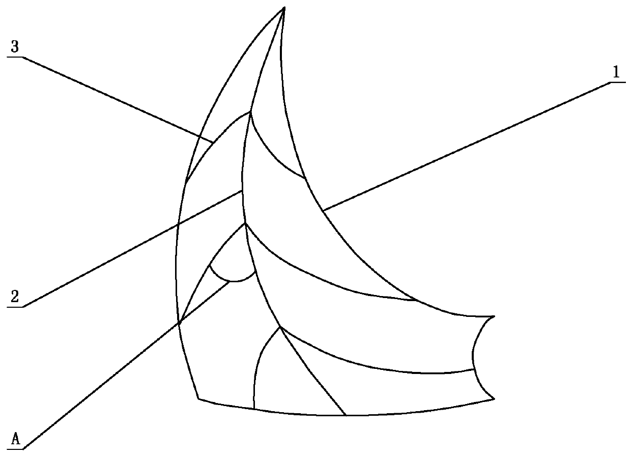
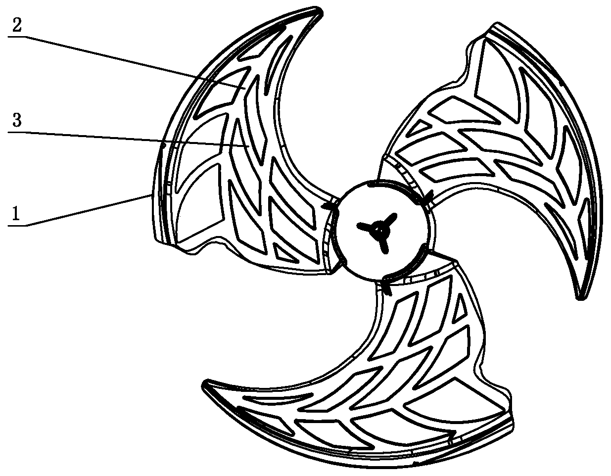
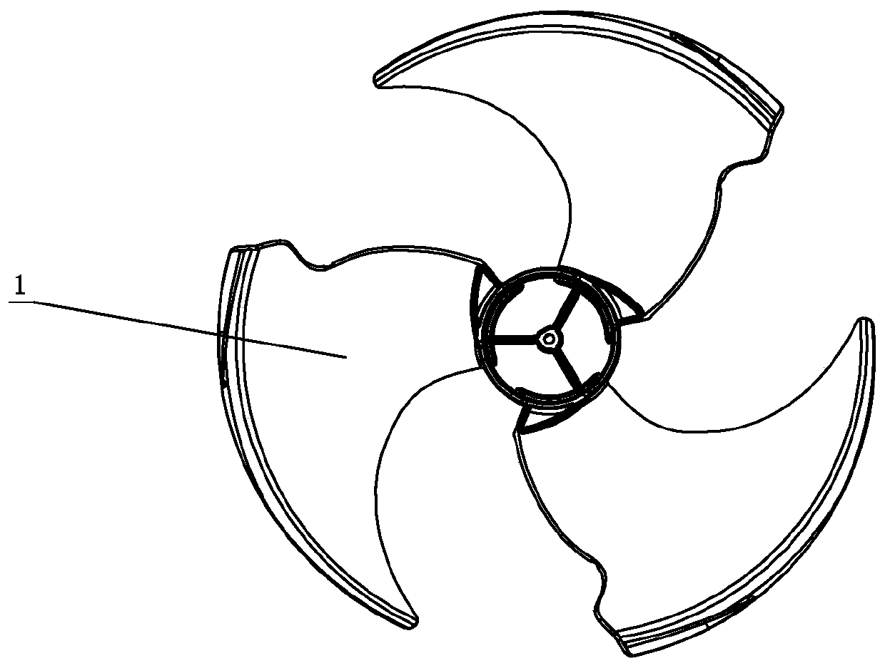
[0026] see Figure 1-Figure 3 , an axial flow fan with a rib structure, comprising a blade 1, the blade 1 is respectively provided with more than one first rib 2 and second rib 3 in the longitudinal direction and the transverse direction, so that several ribs are formed on the blade 1 Bosses, and an airflow guiding area is formed between two adjacent bosses; wherein, more than one second rib 3 extends from one or both sides of the first rib 2, and the first rib 2 and the second rib 3 Spline curves in arc shape or polyline combination respectively. Polylines include arcs and lines.

[0027] The first rib 2 and the second rib 3 increase the strength and rigidity of the blade 1 , reduce the deformation of the blade during the operation of the axial flow fan, and reduce the risk of the blade 1 being broken.

[0028] The first and second ribs 2, 3 and the small boss structure on the surface of the blade 1 will generate turbulence when the blade 1 rotates, thereby destroying the b...

no. 2 example

[0033] see Figure 4 An axial flow fan with rib structure is different from the first embodiment in that the second rib 3 on one side of the first rib 2 is provided with a third rib 4, and the third rib 4 is longitudinally arranged on the blade 1 on.

[0034] The cross-sections of the first, second and third ribs 2, 3, and 4 are rectangular, stepped, triangular, semicircular or polygonal, and the dimensions of the first, second, and third ribs 2, 3, and 4 are respectively = 1-3 times of the maximum thickness of the blade 1, the cross-sectional area of ​​the second rib 3=50%-70% of the cross-sectional area of ​​the first rib 2, the third rib 4=25%-50% of the first rib 2 Sectional area.

[0035] A third rib 4 is connected between two adjacent second ribs 3 on one side of the first rib 2 , so that two adjacent second ribs 3 and third ribs 4 form a closed loop.

[0036] The third reinforcing rib 4 is separated from the 1 / 2 of the second reinforcing rib 3 on the side of the firs...


PUM


Abstract

Disclosed is an axial flow fan with a reinforcing rib structure. The axial flow fan comprises blades, wherein each blade is provided with one or more first reinforcing ribs in the longitudinal direction and one or more second reinforcing ribs in the transverse direction, so that a plurality of bosses are formed in each blade, and an airflow guiding area is formed between every two adjacent bosses;the one or more second reinforcing ribs extend out of the one side or the two sides of each first reinforcing rib, and each first reinforcing rib and the corresponding second reinforcing ribs are respectively arc-shaped or spline curves formed by combining multiple sections of lines; and the first reinforcing ribs and the second reinforcing ribs are respectively arranged on the suction surface ofeach blade, the central lines of the first reinforcing ribs and the second reinforcing ribs are respectively arc-shaped or spline curves formed by combining multiple sections of lines, and the bending directions of the central lines of the first reinforcing ribs and the second reinforcing ribs on each blade are consistent with the streamline direction of the surface of each blade. The axial flowfan effectively improves the strength of the blades, reduces the running resistance when the blades run, and further reduces the power consumption of the fan.

Description

technical field [0001] The invention relates to an axial flow fan, in particular to an axial flow fan with a rib structure. Background technique [0002] The blades will be subjected to air resistance during rotation, and if the resistance is too large, the power consumption of the fan will be increased. And blade is generally provided with reinforcing rib, to increase the intensity of blade, but the mode that reinforcing rib is set is single, and the reinforcing rib that has is arranged on the root of blade, only plays the effect of protection. Therefore room for further improvement. Contents of the invention [0003] The purpose of the present invention is to provide an axial flow fan with ribbed structure, which has a reasonable structure, low power consumption, high strength, effectively reduces fan energy consumption, and improves blade strength, so as to overcome the deficiencies in the prior art place. [0004] An axial flow fan with rib structure designed accord...

Claims


Application Information

Patent Timeline
IPC IPC(8): F04D29/38
CPCF04D29/386F04D29/388
Inventor 李骏程守炤李嘉盛覃万翔
Owner GUANGDONG SUNWILL PRECISING PLASITC CO LTD
Why Eureka
Try Eureka