
High order temperature compensation current reference source

A high-order temperature compensation, current reference source technology, applied in the power supply field, can solve the problem of not very good temperature characteristics, and achieve the effect of excellent performance

Inactive Publication Date: 2006-01-25
UNIV OF ELECTRONICS SCI & TECH OF CHINA
View PDF1 Cites 16 Cited by
  • Summary
  • Abstract
  • Description
  • Claims
  • Application Information

AI Technical Summary

Problems solved by technology

The technical scheme has been simulated by computer. In the range of -25 degrees to 75 degrees, the output reference current changes by 1.4%, which is 140ppm, which shows that its temperature characteristics are not very good.

Method used


Image

  • High order temperature compensation current reference source
  • High order temperature compensation current reference source
  • High order temperature compensation current reference source

Examples


Embodiment Construction

[0031] In order to have a further understanding of the high-order temperature-compensated current reference source proposed by the present invention, the principle, circuit structure and specific implementation will be described in detail below in conjunction with the accompanying drawings.

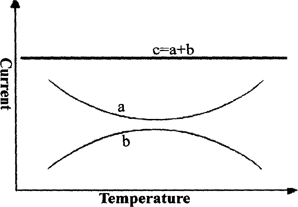
[0032] Such as figure 1 Shown: Curve a is the voltage or current temperature characteristic curve with the opening upward after the first-order temperature compensation, curve b is the voltage or current temperature characteristic curve with the opening downward after the first-order temperature compensation, and curve c is the curve a and Curve b is the temperature characteristic curve of voltage or current after appropriate proportion superimposition. Considering various non-ideal effects in various integrated circuits, curve c will not be a standard straight line in the end, and the straight line is only used for principle illustration.

[0033] The following are respectively Figure...


PUM


Abstract

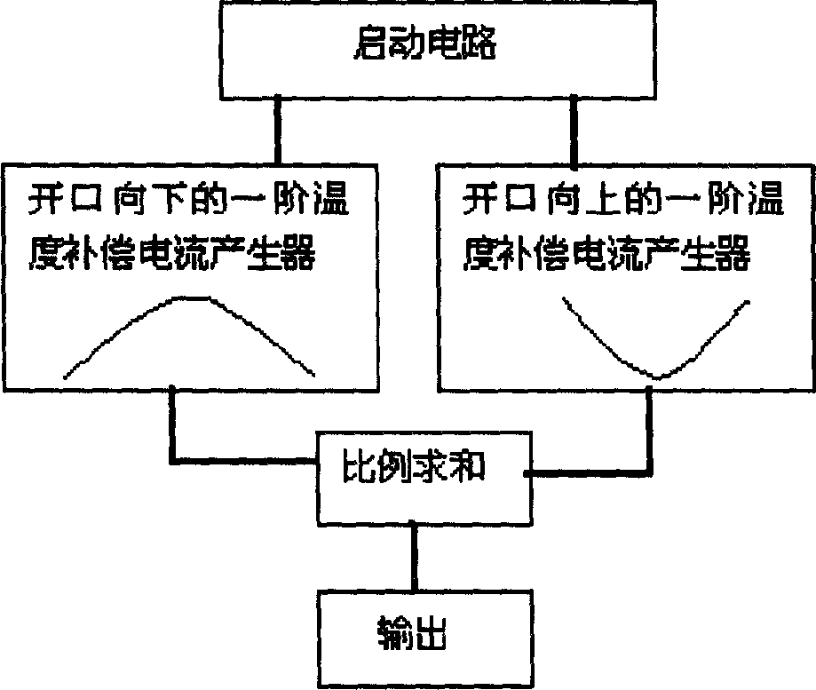
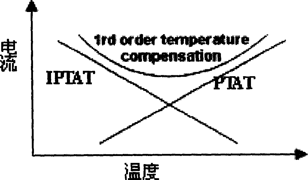
This invention provides a high-order temperature compensation circuit primary standard source including: a starting circuit providing start offset voltages for a first order temperature compensation current generator, a second first order temperature compensation current generator and a ratio summing circuit, a first order temperature compensation current generator for generating a first order temperature compensation current, the temperature character curve is a high-order one with an upward open-end, a second first order temperature compensation current generator generating an other one, the temperature character curve is a high order one with a downward open-end, a ratio summing circuit summing in proportion to the compensated currents generated by the two generators, an output circuit outputting current after the high-order temperature compensation.

Description

technical field [0001] The invention belongs to the technical field of power supplies, and in particular relates to a temperature compensation current reference source. Background technique [0002] The function of the current reference source is to provide reference currents to other functional modules in the circuit. It is a very important functional module in analog integrated circuits. It often provides reference currents for oscillators, filters, digital-to-analog conversion and precise time delay modules. For current, there is no loss when transmitting on long metal wires, but voltage has loss, so in analog circuits with long interconnecting metal wires, current reference sources are more preferred. In addition, if the circuit adopts the current mode, it will work at a higher frequency than the voltage mode, which will increase the speed of the circuit. However, the accuracy and accuracy of the current mode circuit when it works in a large temperature range is directly...

Claims


Application Information

Patent Timeline
Patent Type & Authority Applications(China)
IPC IPC(8): G05F1/46G05F3/08
Inventor 周号张波李肇基
Owner UNIV OF ELECTRONICS SCI & TECH OF CHINA
Learn More