Electromagnetic operation device

An electromagnetic operation and electromagnetic technology, applied in circuits, electrical switches, electrical components, etc., can solve the problems of vacuum valve opening time deviation, difficulty in saving space, and inability to stably cut off the system, and achieve the effect of stable disconnection.

Inactive Publication Date: 2006-01-25
HITACHI LTD
View PDF2 Cites 12 Cited by
  • Summary
  • Abstract
  • Description
  • Claims
  • Application Information

AI Technical Summary

Problems solved by technology

As a result, the disconnection timing of the vacuum valves of each phase deviates, and there is a problem that stable shutdown of the system cannot be performed.
[0007] In addition, as the size of the electromagnet increases, the size of the electromagnetic operator and its controller increases accordingly, and it is difficult to save space.

Method used


Image

  • Electromagnetic operation device
  • Electromagnetic operation device
  • Electromagnetic operation device

Examples


Embodiment 1

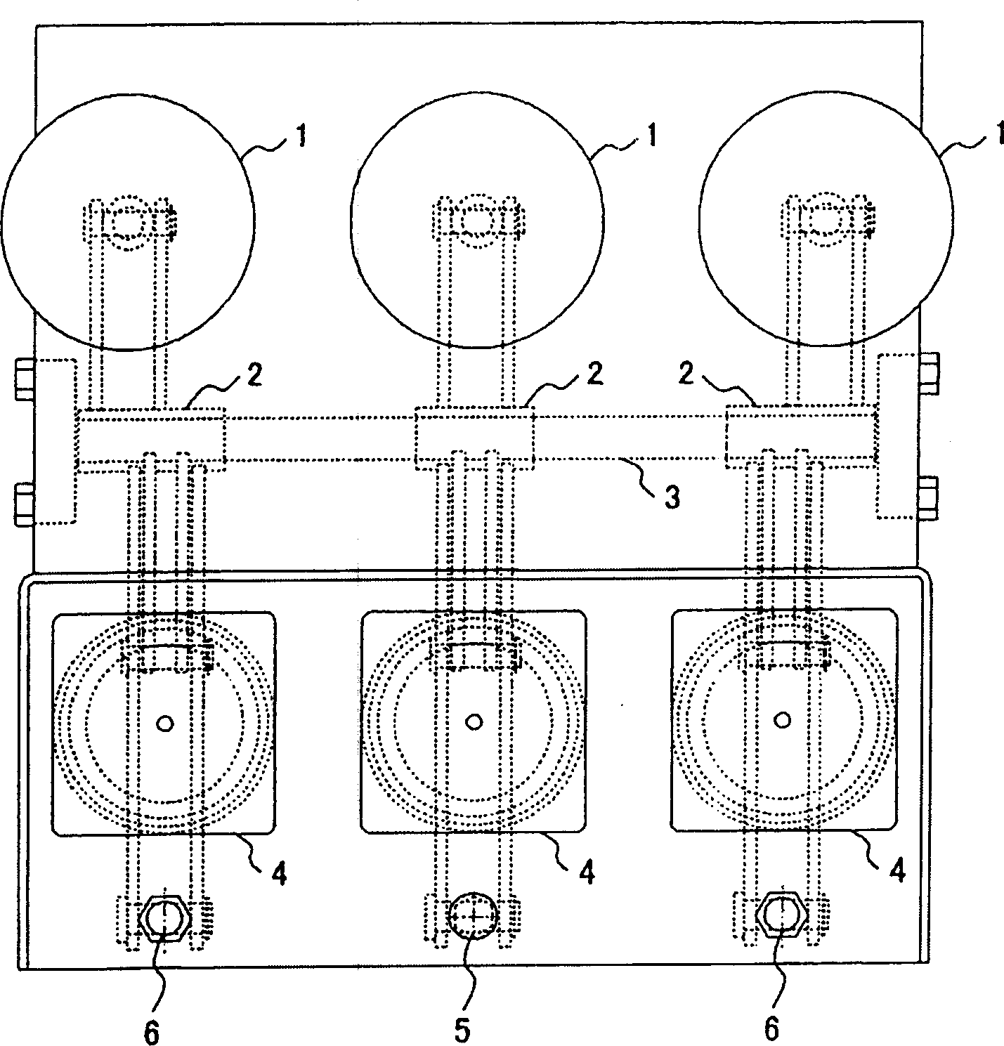
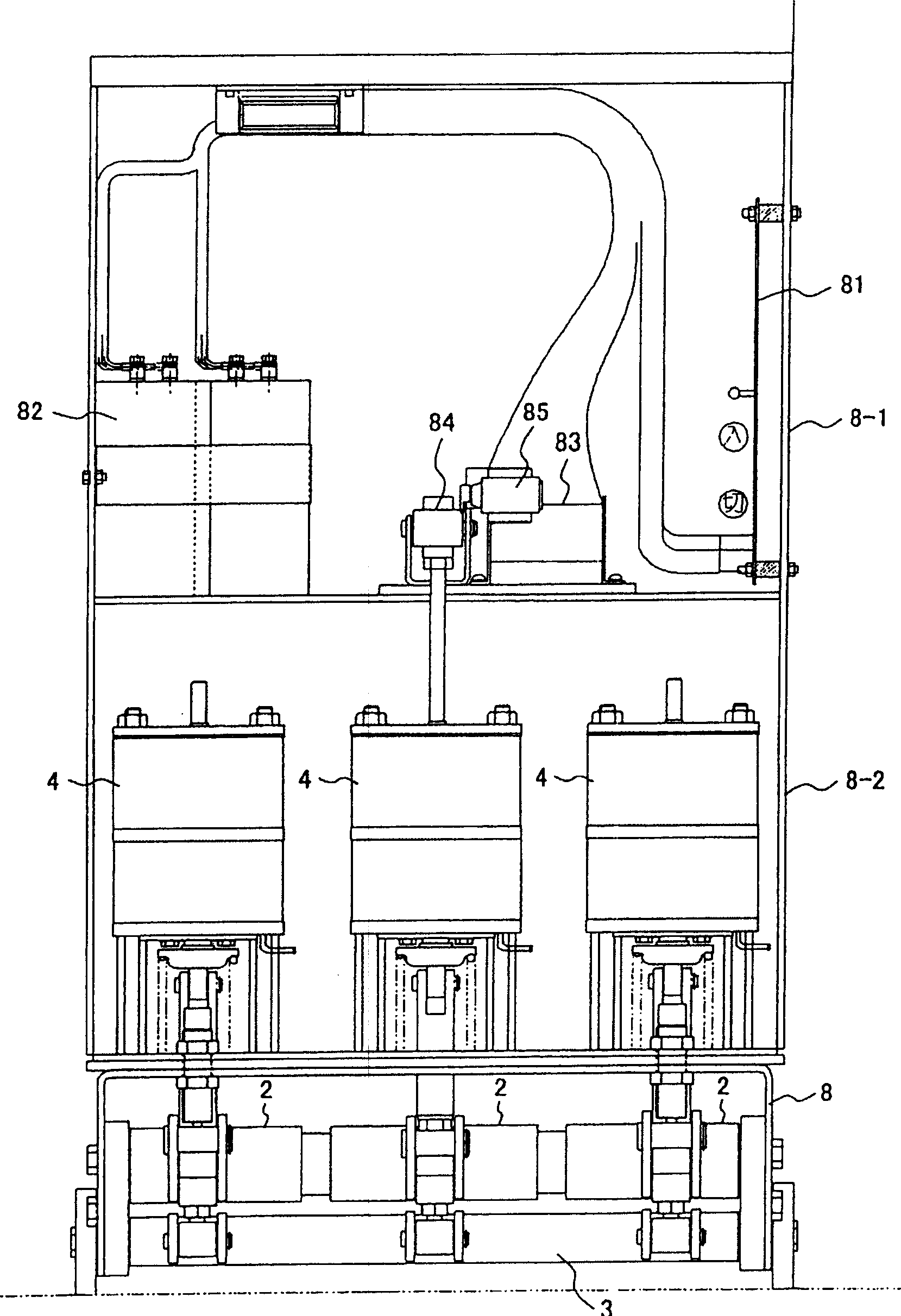
[0023] figure 1 is a top view of the electromagnetic operating device of the present invention, figure 2 is the front view including the electromagnetic manipulator and controller, Figure 3A , Figure 3B is a side view including the main shaft and the three-phase connecting shaft.

[0024] Such as figure 1 As shown, the vacuum valves 1 of each phase are respectively connected to the electromagnetic operator 4 through the main shaft 2 . The main shafts 2 freely start to move in each phase, and are connected by a three-phase connection shaft 3 as described later, so that synchronization among the main shafts 2 is obtained.

[0025] Such as figure 2 As shown, the electromagnetic operating device is accommodated in a box-shaped multi-segment frame body 8, controllers such as a control board 81 and a capacitor 82 are accommodated in the upper segment 8-1, and the electromagnetic operator 4 is accommodated in the middle segment 8-2. . As shown in the figure, the upper sect...

Embodiment 2

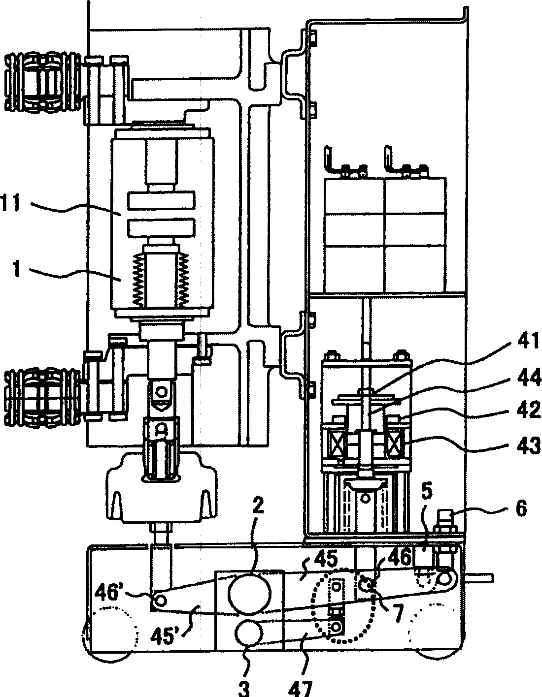
[0039] A second embodiment of the present invention will be described below. Figure 5 , Image 6 It is an embodiment in which the three-phase connection shaft 3 is arranged on the upper part of the electromagnetic operator 4 .

[0040] The three-phase connection shaft 3 is arranged on the upper side of the electromagnetic operator 4 , and the main shaft 2 is arranged on the lower side of the electromagnetic operator 4 . The connection of the two axes is performed by the rod 44 of the electromagnetic operator 4 . That is, since the rod 44 is connected to the vane 45 of the main shaft 2 via the fulcrum 46 , the movement of the rod 44 can be transmitted to the vane 47 of the upper three-phase connection shaft 3 . Thus, the three-phase connection shaft 3 can achieve synchronization among the respective main shafts 2 .

Embodiment 3

[0042] A third embodiment of the present invention will be described below. Figure 7 This is an example in which the three-phase connection shaft 3 is arranged on the vacuum valve 1 side. The difference from the first embodiment is that the three-phase connecting shaft 3 is arranged on the lower part of the main shaft 2 on the side of the vacuum valve 1 . The connecting portion 7 is provided between the vane 45' on the vacuum valve 1 side of the main shaft 2 and the vane 47 of the three-phase connecting shaft 3. The linked action is the same as in the first embodiment.

[0043]The three embodiments described above should be appropriately selected according to the configuration of the electromagnetic operation device. For the first and third embodiments, the main shaft and the three-phase connection shaft are arranged in the same frame area, so it is easy to assemble or Adjustment. On the other hand, the second embodiment has a structure that does not require a connecting p...


PUM


Abstract

The aim of the invention is to aim at synchronization among three phases by restraining fluctuation of movement of each main shaft facing a three-phase vacuum valve. An electromagnetic operation device, comprising electromagnetic operators 4 each paired with a vacuum valve 1 of each phase of three phases, is equipped with main shafts 2 that can operate independently for each phase and a three-phase connecting shaft 3 that synchronizes the operation of the three phases in accordance with the operation of each main shaft. The rod 44 of the electromagnetic operator 4 is connected with the blade 45 of the main shaft 2 at the fulcrum 46 and the blade 47 of the three-phase connecting shaft 3 is connected with the blade 45 of the main shaft 2 by the linkage 7. The motion of a main shaft 2 that has operated quicker than the others is transmitted to the other main shafts via the three-phase connecting shaft 3 so as to synchronize the operation of the three phases.

Description

technical field [0001] The present invention relates to an electromagnetic operating device, in particular to an electromagnetic operating device suitable for using electromagnetic force to switch on and off an interrupter such as a circuit breaker. Background technique [0002] When operating an interrupter such as a circuit breaker, an electromagnetic operator that performs on-off using an electromagnetic force generated by an electromagnet is used (see Patent Document 1). [0003] In addition, there is also a hybrid manipulator that uses the electromagnetic attraction force of an electromagnet when turning on and uses a permanent magnet when holding it (see Patent Document 2). [0004] [Patent Document 1] JP-A-2002-217026 [0005] [Patent Document 2] JP-A-2001-216875 [0006] When the above-mentioned electromagnetic operator is used for the vacuum valve of the three-phase power system, usually, the electromagnetic operator and the vacuum valve of each phase are in one-t...

Claims


Application Information

Patent Timeline
Patent Type & Authority Applications(China)
IPC IPC(8): H01H33/38
CPCH01H33/6662H01H33/022H01H2033/6667H01H33/38
Inventor 杉野友启森田步土屋贤治小林将人
Owner HITACHI LTD
Why Eureka
Try Eureka