Digital broadcast receiving apparatus
A technology of digital broadcasting and receiving devices, applied in broadcasting receiving circuits, simultaneous broadcasting of multiple pieces of information, specific information broadcasting systems, etc., can solve problems such as not being able to fully understand the content of data broadcasting
- Summary
- Abstract
- Description
- Claims
- Application Information
AI Technical Summary
Problems solved by technology
Method used
Image
Examples
no. 1 example
[0031] A first embodiment of the present invention is described below.
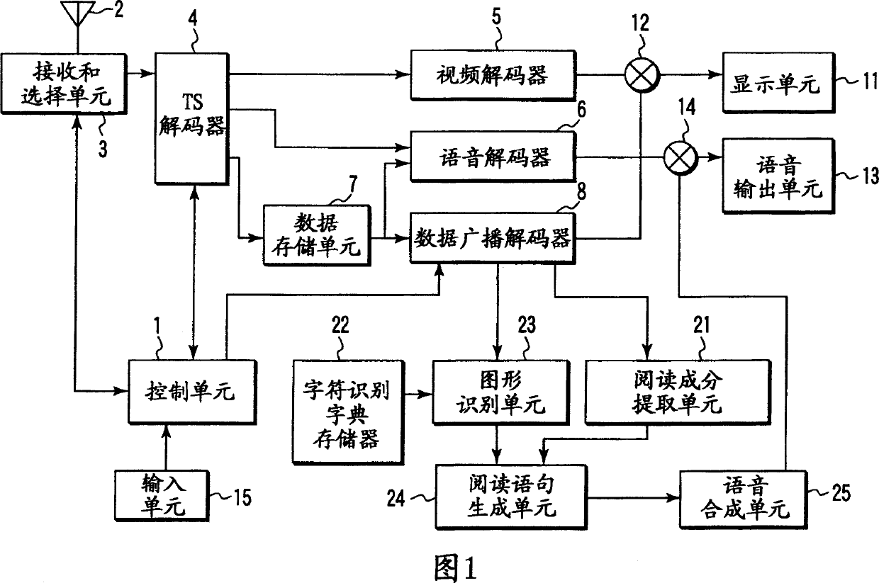
[0032] FIG. 1 is a block diagram showing the structure of a vehicle-mounted broadcast receiving apparatus according to a first embodiment of the present invention.
[0033] The vehicle-mounted broadcast receiving device includes a control unit 1, which controls the overall operation of the device. The device also includes a television (TV) antenna 2 , a TV channel selection unit 3 and a transport stream (TS) decoder 4 .
[0034] The TV channel selection unit 3 selects radio waves of a preselected TV broadcast station from, for example, radio waves of terrestrial digital TV broadcasts received by the TV antenna 2 . The TS decoder 4 separates a signal (MPEG2 transport stream) generated by demodulating the selected radio wave into a video stream, a voice stream, and a data broadcast stream.
[0035] The vehicle broadcast receiving device also includes a video decoder 5 , a voice decoder 6 , a data storage ...
no. 2 example
[0078] A second embodiment of the present invention is described below. For the same constituents as those of the first embodiment shown in FIG. 1, description thereof is omitted.
[0079] FIG. 9 is a block diagram showing the structure of a vehicle-mounted broadcast receiving device according to a second embodiment of the present invention. This device does not include the character recognition dictionary memory 22 and the pattern recognition unit 23 shown in FIG. 1 .
[0080] The operation of the in-vehicle broadcast receiving device according to the second embodiment will be described below.
[0081] When the user operates the input unit 15 to set the device in the voice reading mode, the control unit 1 controls the data broadcast decoder 8 to provide the reading component extraction unit 21 with the BML file "news" contained in the data broadcast stream stored in the data storage unit 7. .bml" (see Figure 3) and binary table file "news.tbl" (see Figure 4).
[0082] Afte...
no. 3 example
[0092] A third embodiment of the present invention is described below. For the same constituents as those of the first embodiment shown in FIG. 1, description thereof is omitted.
[0093] Fig. 12 is a block diagram showing the structure of a vehicle-mounted broadcast receiving device according to a third embodiment of the present invention. This device does not include the reading component extraction unit 21 shown in FIG. 1, and in addition, a pattern recognition unit 31 is used instead of the pattern recognition unit 23 shown in FIG.
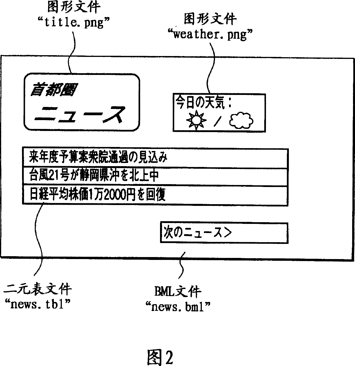
[0094] The data broadcast decoder 8 of this in-vehicle broadcast receiving device has a function of decoding the data broadcast stream read from the data storage unit 7 to generate image data of a complete output screen and then supplying it to the pattern recognition unit 31 . The image data of the complete output screen is an image of the output screen of the display unit 11, as shown in FIG. 2 .
[0095] The pattern recognition unit 31 ha...
PUM
 Abstract
Description
Claims
Application Information
 - R&D
- Intellectual Property
- Life Sciences
- Materials
- Tech Scout
- Unparalleled Data Quality
- Higher Quality Content
- 60% Fewer Hallucinations
Browse by: Latest US Patents, China's latest patents, Technical Efficacy Thesaurus, Application Domain, Technology Topic, Popular Technical Reports.
© 2025 PatSnap. All rights reserved.Legal|Privacy policy|Modern Slavery Act Transparency Statement|Sitemap|About US| Contact US: help@patsnap.com


