Suction structure of air cleaner

An air purifier and suction port technology, applied in air conditioning systems, space heating and ventilation, chemical instruments and methods, etc., can solve the problems of low air purification efficiency and smooth air circulation, so as to improve work efficiency and purchase Desire, beautiful appearance

Inactive Publication Date: 2006-02-01
LG ELECTRONICS (TIANJIN) APPLIANCES CO LTD
View PDF0 Cites 4 Cited by
  • Summary
  • Abstract
  • Description
  • Claims
  • Application Information

AI Technical Summary

Problems solved by technology

[0015] But above-mentioned existing air cleaner 10 only sucks in air from the suction grille 12 " of air cleaner 10 lower ends, only discharges purified air from discharge grille 16 " of air cleaner 10 upper ends, exists and can not carry out air circulation smoothly, The defect of low air purification efficiency

Method used


Image

  • Suction structure of air cleaner
  • Suction structure of air cleaner
  • Suction structure of air cleaner

Examples


Embodiment Construction

[0069] Preferred embodiments of the air cleaner of the present invention will be described in detail below with reference to the accompanying drawings.

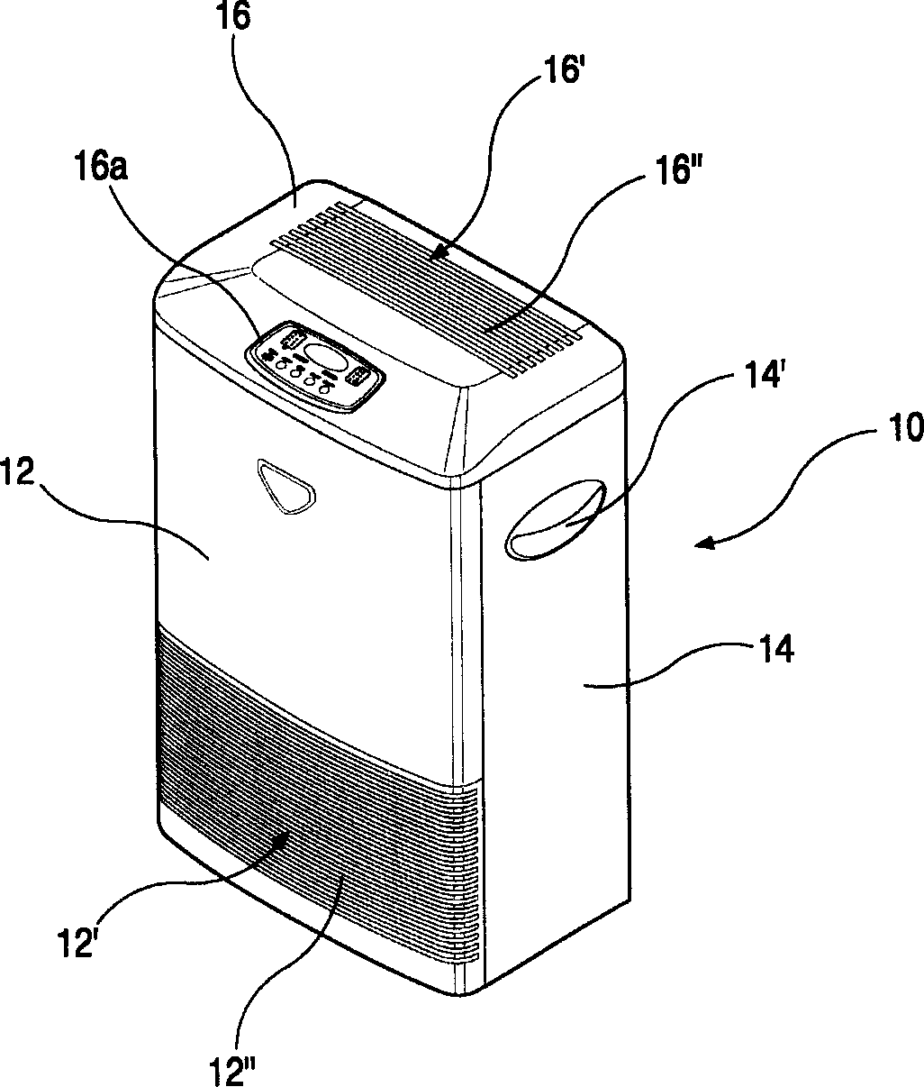
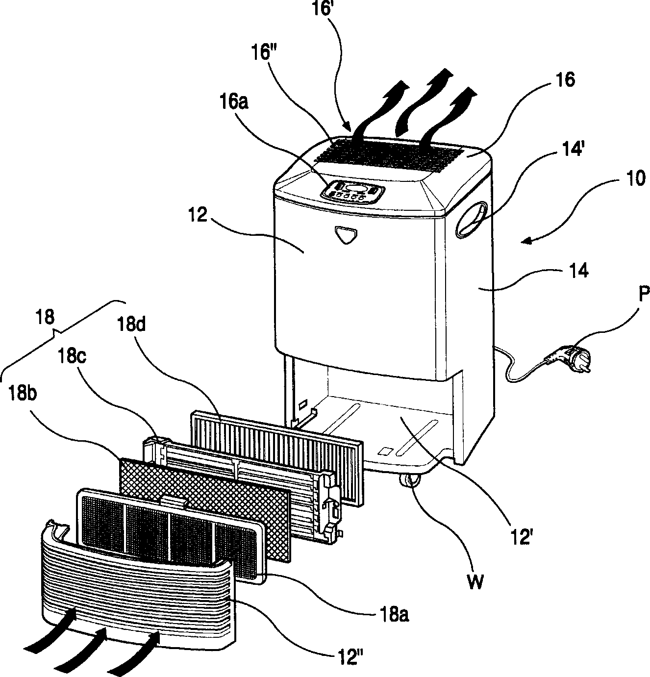
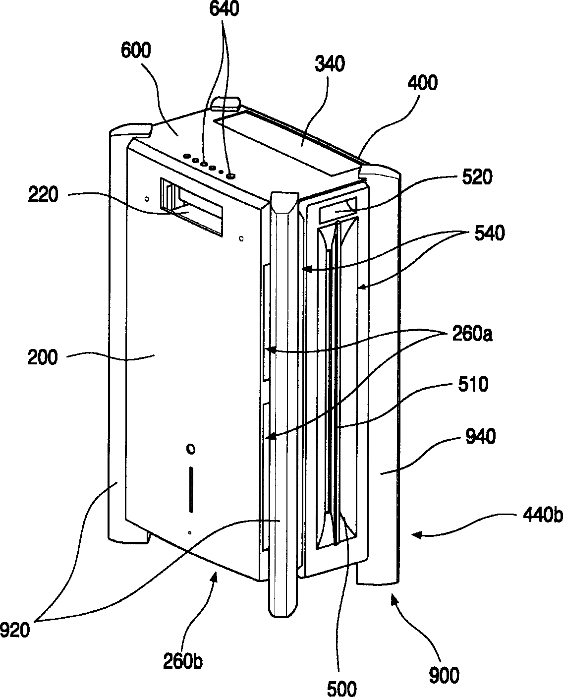
[0070] image 3 It is a three-dimensional schematic diagram of an air purifier in a preferred embodiment of the present invention; Figure 4 It is a schematic diagram of an exploded perspective view of an air purifier according to a preferred embodiment of the present invention; Figure 5 It is a three-dimensional schematic diagram of the front frame of the air purifier according to the preferred embodiment of the present invention; Figure 6 It is a three-dimensional schematic diagram of the front frame combined with the front panel of the air cleaner according to the preferred embodiment of the present invention.

[0071] Figure 7 It is a three-dimensional schematic diagram of an air purifier filter assembly in a preferred embodiment of the present invention; Figure 8 It is a three-dimensional schematic diagram of an ...


PUM


Abstract

An air sucking structure of air cleaner has a front sucking opening between front panel and its frame, a back sucking opening between back panel and its frame, and two lateral sucking openings. Its advantages are high air flow and beautiful appearance.

Description

technical field [0001] The present invention relates to an air purifier, and in particular to an air purifier suction structure capable of inhaling air from the front, rear, left, and right sides of the air purifier. Background technique [0002] In recent years, with the increasingly serious air pollution, the air contains harmful substances and polluted dust. If inhaled directly, it will cause adverse effects on the human body. Therefore, air purifiers of different structures that filter the above-mentioned harmful substances and polluted dust are widely used by people. [0003] figure 1 It is a three-dimensional schematic diagram of an existing air purifier; figure 2 It is an exploded three-dimensional schematic diagram of a filter in an existing air purifier. As shown in the figure, the air cleaner 10 is composed of a front panel 12 forming a front appearance, a side panel 14 forming a side appearance, a rear panel (not shown) forming a rear appearance, and an upper...

Claims


Application Information

Patent Timeline
Patent Type & Authority Applications(China)
IPC IPC(8): B01D46/00F24F3/16
Inventor 徐正尚崔圭晟
Owner LG ELECTRONICS (TIANJIN) APPLIANCES CO LTD
Why Eureka
Try Eureka