Drainage sluice for water resource facilitiea

A technology of water conservancy and facilities, applied in irrigation pipelines, applications, buildings, etc., can solve the problems of low safety factor, simple equipment, high risk, etc., and achieve the effect of convenient operation and control of water flow

Inactive Publication Date: 2006-02-01
余刚强
View PDF0 Cites 12 Cited by
  • Summary
  • Abstract
  • Description
  • Claims
  • Application Information

AI Technical Summary

Problems solved by technology

Simple equipment, time-consuming and labor-intensive, low safety factor, high risk

Method used


Image

  • Drainage sluice for water resource facilitiea
  • Drainage sluice for water resource facilitiea
  • Drainage sluice for water resource facilitiea

Examples


Embodiment Construction

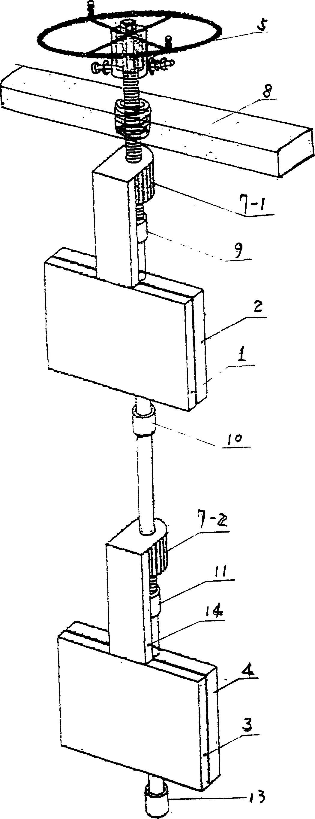
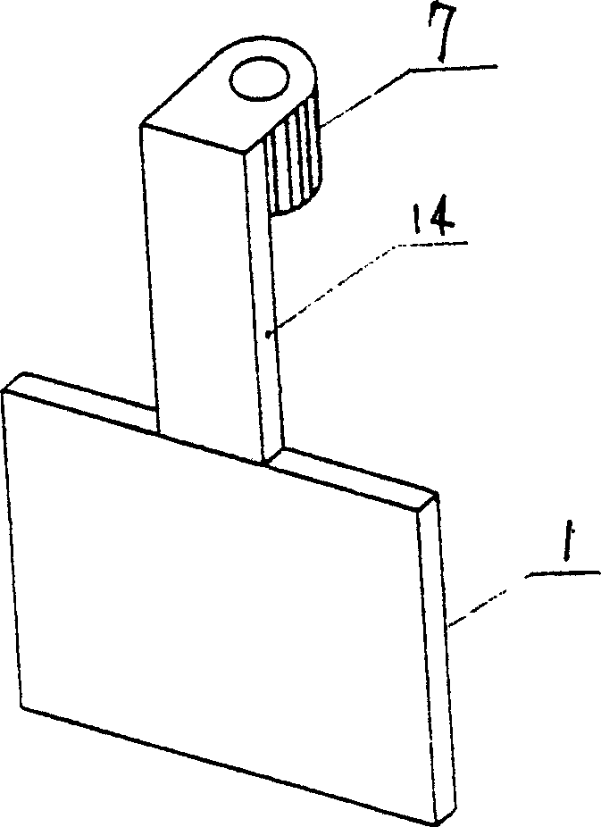
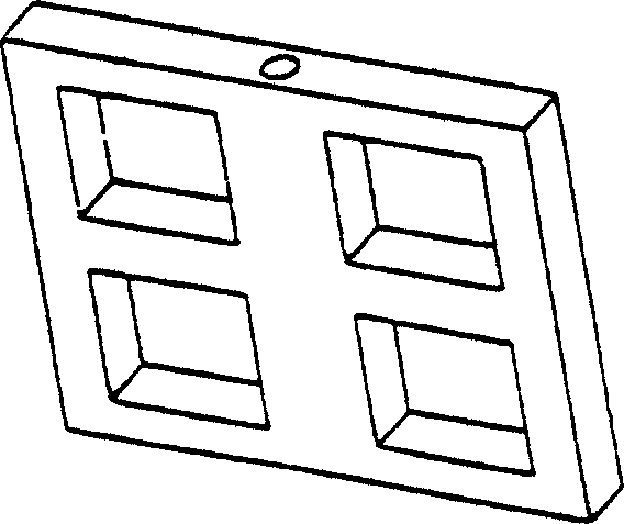
[0017] Such as figure 1 A water conservancy facility drainage gate as shown in this embodiment includes a lifting plate (5), a load-bearing member (8), a support rod (6), an internal threaded sleeve (7), and a mid-limit inner water retaining plate (1) , middle limit inner water retaining plate limit ring (9), middle limit outer water retaining plate (2), middle limit outer water retaining plate limit ring (10), lower limit inner water retaining plate (3), lower limit inner water retaining plate Plate limit ring (11), lower limit outer water retaining plate (4), lower limit outer water retaining plate limit ring (13), in the present embodiment, the lifting disc (5) relies on the inner hexagon of the disc shaft sleeve and the pole ( 6) The outer hexagonal shaft at the top and the fastening screw are fastened to the top of the support rod (6), and the support rod (6) below the lifting plate (5) is sequentially installed with a load-bearing member (8), an internal thread sleeve (7...


PUM


Abstract

A draining gate for the water conservancy facilities is sequentially from top to bottom composed of lift wheel, load-bearing part, supporting rod, internal spiral sleeve, middle retaining plate and its position limiting ring, and lower retaining plate and its position-limiting ring.

Description

technical field [0001] The invention relates to a water conservancy facility, in particular to a water conservancy facility drainage gate. Background technique [0002] At present, rural water conservancy facilities, including reservoirs, ponds, and dam drainage system gates are very backward, and most of them are still in the "wooden pile soil filling method". The equipment is simple, time-consuming and labor-intensive, the safety factor is low, and the danger is great. Even when draining water, find young adults with good water quality to enter the water for treatment. Over the years, only one has caused thousands of casualties in rural areas, not to mention the waste of various resources and the resulting disputes among villagers. Contents of the invention [0003] In order to overcome the above problems, the present invention provides a simple, durable, safe and reliable drainage gate for rural water conservancy...

Claims


Application Information

Patent Timeline
Patent Type & Authority Applications(China)
IPC IPC(8): E02B13/02
Inventor 余刚强
Owner 余刚强
Why Eureka
Try Eureka