Method for arranging electronic ballast in high strength gas discharge lamp

A technology of electronic ballasts and gas discharge lamps, which is applied in the direction of circuit layout, components of lighting devices, cooling/heating devices of lighting devices, etc.

Inactive Publication Date: 2006-02-08
叶更生
View PDF0 Cites 1 Cited by
  • Summary
  • Abstract
  • Description
  • Claims
  • Application Information

AI Technical Summary

Problems solved by technology

[0003] In order to solve the problem that electronic ballasts cannot be used well with high-intensity gas discharge lamps, the present invention provides a method for placing electronic ballasts in high-intensity gas discharge lamps, which can effectively solve the problem of electronic ballasts. The heat dissipation problem of the ballast can be significantly improved, and the service life of the electronic ballast can be significantly improved

Method used


Image

  • Method for arranging electronic ballast in high strength gas discharge lamp
  • Method for arranging electronic ballast in high strength gas discharge lamp
  • Method for arranging electronic ballast in high strength gas discharge lamp

Examples


Embodiment Construction

[0009] One of the embodiments of the present invention:

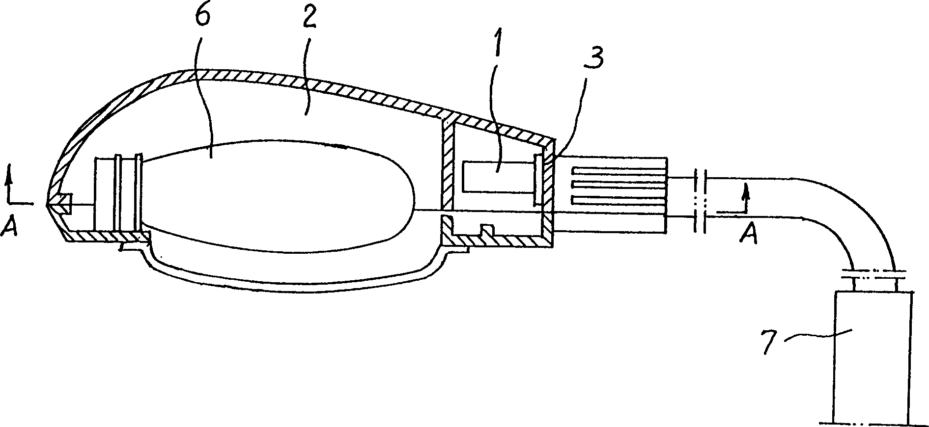
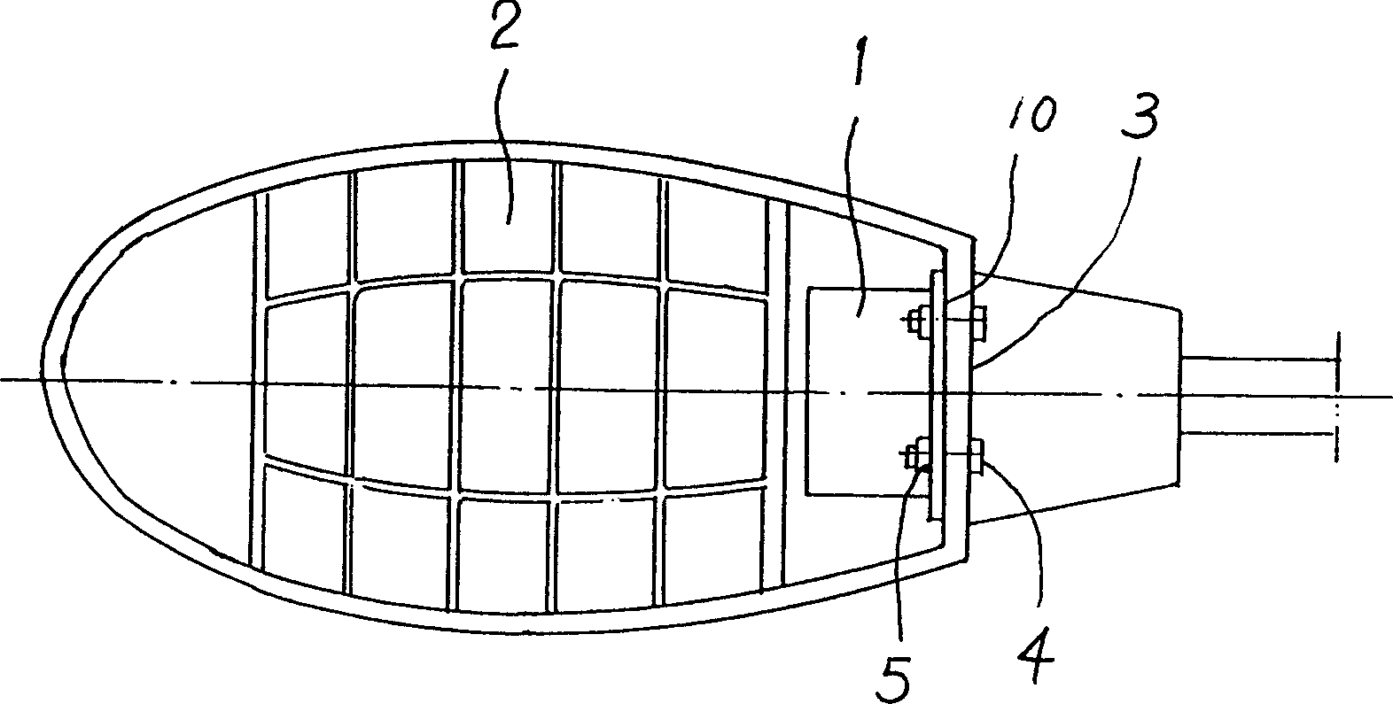
[0010] like Figure 1 to Figure 2 As shown, a plane of the electronic ballast 1 is placed on the inner surface of the rear wall 3 of the lamp housing 2, and finally the electronic ballast 1 is fastened to the inner surface of the rear wall 3 of the lamp housing 2 by bolts 4 and nuts 5 just go up. 6 is a light bulb among the accompanying drawings, and 7 is a lamppost.

[0011] Another embodiment of the invention:

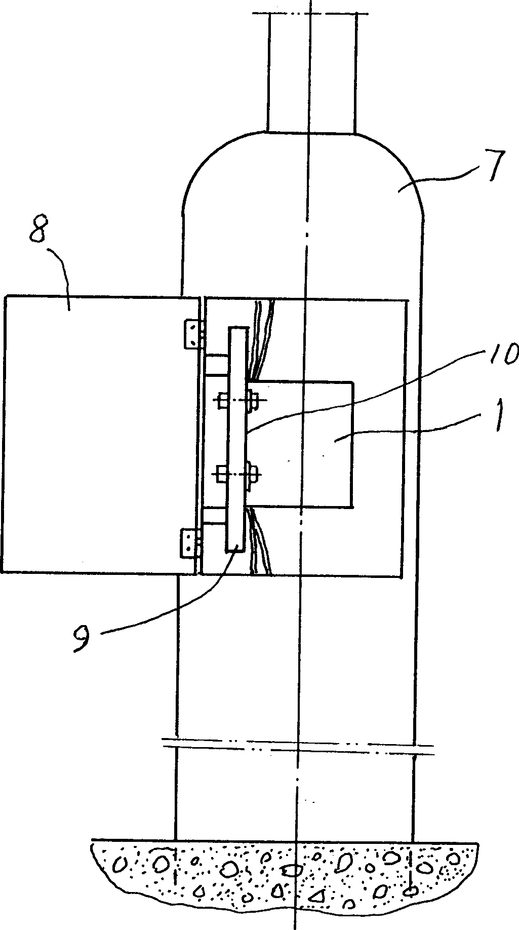
[0012] like image 3 The solution shown is to place a flat surface of the electronic ballast 1 on a flat plate 9 inside the lamp post door 8 at the lower part of the lamp post 7 for mounting fuses and other components.

[0013] During implementation, the largest plane of the electronic ballast 1 should be in contact with one of the planes of the lamp housing 2 or the lamp post 7 as much as possible, so as to expand the heat dissipation area and speed up the heat dissipation. In addition, in order to furth...


PUM


Abstract

The method of setting electronic ballast inside the high strength gas discharge lamp is that one of the electronic ballast planes is set on one plane of the lamp casing or lamp column of the high strength gas discharge lamp by means of fastener. The present invention features planar contact between the electronic ballast and the amp casing or lamp column of the high strength gas discharge lamp to dissipate the heat the electronic ballast produces via heat conduction. The said method can maintain the temperature raising of the electronic ballast within certain range, avoid exposure of the electronic ballast to sun and rain, raise operation stability and prolong service life. The present invention makes it possible to apply electronic ballast with low power consumption to save great amount of electric energy.

Description

Technical field [0001] The present invention is a method of locating an electronic ballast in a high intensity discharge lamp. Background technique [0002] High-intensity discharge lamps (HID) such as high-pressure sodium lamps and metal halide lamps are newly developed energy-saving light sources in recent years. They have low energy consumption, high brightness, and small size, which can create a bright and beautiful nighttime living environment for people. It is welcomed by people and is being promoted and applied in many cities in my country. However, the disadvantage is that the supporting ballast of this kind of lamp is an inductive ballast. This kind of inductive ballast consumes a lot of power, and nearly 50% of the electric energy is wasted for nothing. In a tense situation, still using this traditional ballast will inevitably consume a lot of power. High-intensity gas discharge lamps save energy, but the ballast consumes energy. This is a very contradictory thing....

Claims


Application Information

Patent Timeline
IPC IPC(8): F21V23/02F21V29/00F21V29/50F21V29/85
Inventor 叶更生
Owner 叶更生
Why Eureka
Try Eureka