Multi lamp tube control circuit

A technology for controlling circuits and lamps, applied in electric light sources, electrical components, lighting devices, etc., can solve the problem of no picture on the LCD panel and achieve the effect of ensuring normal display

Inactive Publication Date: 2006-02-08
NIKO SEMICON
View PDF0 Cites 1 Cited by
  • Summary
  • Abstract
  • Description
  • Claims
  • Application Information

AI Technical Summary

Problems solved by technology

This phenomenon will cause th

Method used


Image

  • Multi lamp tube control circuit
  • Multi lamp tube control circuit
  • Multi lamp tube control circuit

Examples


Example Embodiment

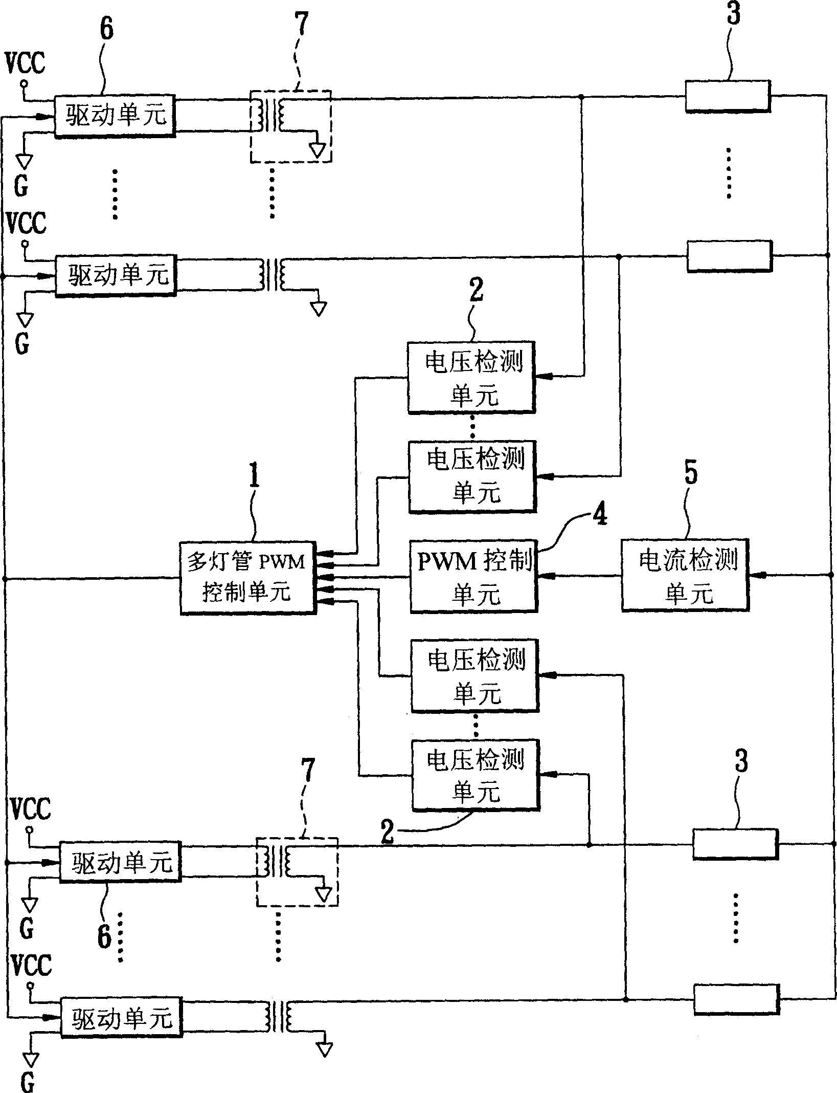
[0026] Please refer to figure 2 , Is a schematic block diagram of the circuit of the first embodiment of the present invention. The multi-lamp control circuit of the present invention is connected to a power supply VCC to drive at least one lamp 3 to emit light, and includes: a multi-lamp PWM control unit 1, at least one voltage detection unit 2, a PWM control unit 4, and a current detection Unit 5, at least one drive unit 6, and at least one transformer 7.

[0027] Refer again figure 2 The voltage detection unit 2 is respectively connected to the lamp tube 3 and the transformer 7 to obtain a load voltage of the lamp tube 3 respectively. The current detection unit 5 is connected to the lamp tube 3 and the PWM control unit 4 to obtain a load current of the lamp tube 3 and transmit it to the PWM control unit 4. The PWM control unit 4 receives the load current to output a pulse width modulation signal.

[0028] The multi-lamp PWM control unit 1 is connected to the drive unit 6, the...


PUM


Abstract

This invention relates to a multi-tube control circuit, used in the condition of no less than one cold negative pole fluorescent tube driven, via the feedback of the tube voltage, controlling the tube, which comprises no less than a driven unit, no less than a transformer linked with the driven unit and the tube, a current testing unit linked with the driven unit and the tube to attain tube's loading current, a PWM control unit linked with the current testing unit to receive the loading current and output a pulse width adjusting signal, no less than a voltage testing unit linked with the tube and the transformer to attain tube's loading voltage, and a multi-tube PWM control unit linked with the driven unit, the voltage testing unit and PWM controlling unit to receive pulse width adjusting signal and the loading voltage and output at least a control signal, transfer to the driven unit to drive at least a switch work.

Description

Technical field [0001] The present invention relates to a multi-lamp control circuit, in particular to a multi-lamp control circuit used for driving at least one cold cathode fluorescent lamp (CCFL) and capable of controlling the lamps through voltage feedback of the lamps. Background technique [0002] Cold cathode fluorescent lamps (CCFL, Cold Cathode Fluorescent Lamp) are used in LCD Panels as the light source of the Backlight System. This kind of cold cathode fluorescent tube is driven by a drive circuit called an inverter (Inverter). Due to technological progress and consumer demand, the size of LCD panels continues to increase, making a single lamp tube no longer meet its lighting requirements, so two or more lamps are required. [0003] The power supply of the TFT panel backlight mainly uses an inverter circuit (Inverter Circuit) that converts direct current DC into alternating current AC to achieve energy conversion and drive cold cathode fluorescent lamps (CCFL) to emit ...

Claims


Application Information

Patent Timeline
IPC IPC(8): H05B41/282H05B41/292
Inventor 杨惠强王耀震
Owner NIKO SEMICON
Why Eureka
Try Eureka