Precise positioner of bonder terminal in coating and injection moulding process

A connector terminal and precise positioning technology, which is applied in the field of injection molding, can solve problems that affect the company's benefits, high failure rate, increase production costs and inspection costs, etc., to improve customer satisfaction, improve economic benefits, and reduce production costs. Effect

Active Publication Date: 2006-02-22
上海元一电子有限公司 +1
View PDF0 Cites 5 Cited by
  • Summary
  • Abstract
  • Description
  • Claims
  • Application Information

AI Technical Summary

Problems solved by technology

Such a high unqualified rate not only increases the production cost and inspection cost, which affects the company's benefits, but also fails to provide qualified products on schedule due to returns and repairs, thus affecting customer satisfaction

Method used


Image

  • Precise positioner of bonder terminal in coating and injection moulding process
  • Precise positioner of bonder terminal in coating and injection moulding process
  • Precise positioner of bonder terminal in coating and injection moulding process

Examples


Embodiment Construction

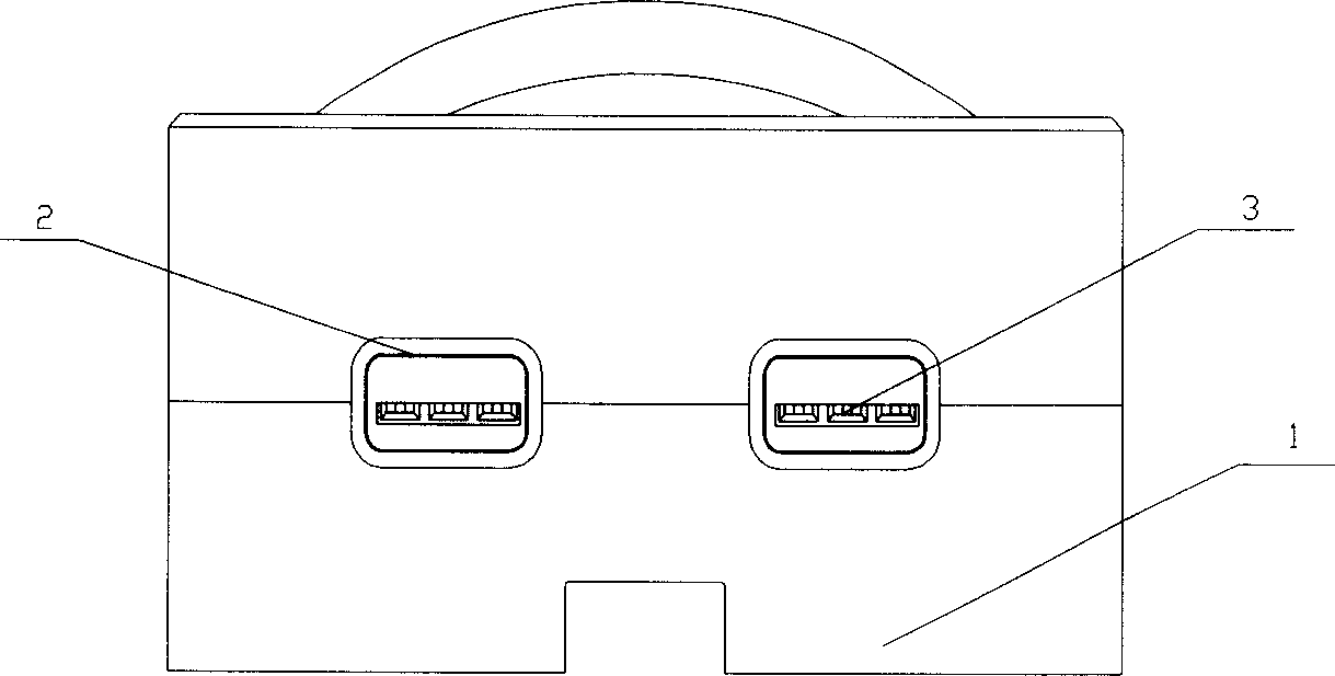
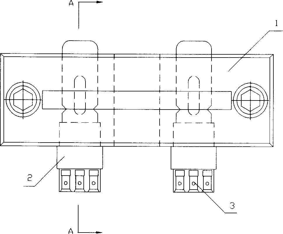
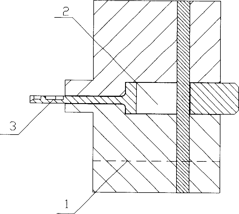
[0011] Such as figure 1 , 2 As shown, a detachable insert 3 connected to the insert 2 is added to the original integral mold core 1 for connector injection. The insert 3 is a movable drawer structure, that is, the insert 3 can be placed inside the insert 2 slide. The length of the insert 3 is greater than the width of the mold core 1, so its sliding inside and outside the insert 2 can be controlled by pushing the part exposed outside the insert 2; a raised positioning pin is provided at one end of the insert 3 , and the corresponding position of the terminal is also provided with a matching round hole; at the same time, the insert 3 is provided with grooves, the number of grooves is consistent with the number of terminals to be processed, and its width is slightly larger than the width of the terminals to be processed.

[0012] The method of processing the connector by using the precise positioning device of the connector terminal in the overmolding process: push out the end...


PUM


Abstract

The invention relates to a precisely locating device for connector terminal in the coating and injection moulding process. Increasing a collapsible drawer type sheet structure- inlaid block into the quadrat of the injection mold core, and by fixing the connector terminal which is going to be manufactured with the groove of the inlaid block and the locating pin, it can reduce greatly the rejection rate in the injection moulding process and increase the economic benefit.

Description

technical field [0001] The invention belongs to the field of injection molding. In particular, it relates to a device for precise positioning of connector terminals in injection molds. Background technique [0002] In the overmolding process of connector terminals, the core of the traditional mold is only provided with terminal fixing holes, and the terminals are fixed by directly inserting the terminals into the fixing holes without any other positioning measures. Since the injection molding will generate a great impact during the injection molding process of the product, only using the traditional terminal fixing hole positioning method will cause the terminal to move backwards, which will affect the qualified rate of the product. If the resulting dimensional tolerance exceeds 1±0.25, it will cause poor contact or open circuit between the product and its accessories. According to statistics, the rate of unqualified products due to the over-tolerance of this dimension is ...

Claims


Application Information

Patent Timeline
Patent Type & Authority Applications(China)
IPC IPC(8): B29C45/36
Inventor 李志君王成丰邵剑峰袁时本
Owner 上海元一电子有限公司
Why Eureka
Try Eureka