
Air purifier

An air purifier, air technology, applied in the direction of air conditioning system, space heating and ventilation, space heating and ventilation details, etc., can solve problems such as difficult air circulation, and achieve the effect of effective work

Inactive Publication Date: 2006-03-01
LG ELECTRONICS (TIANJIN) APPLIANCES CO LTD
View PDF0 Cites 5 Cited by
  • Summary
  • Abstract
  • Description
  • Claims
  • Application Information

AI Technical Summary

Problems solved by technology

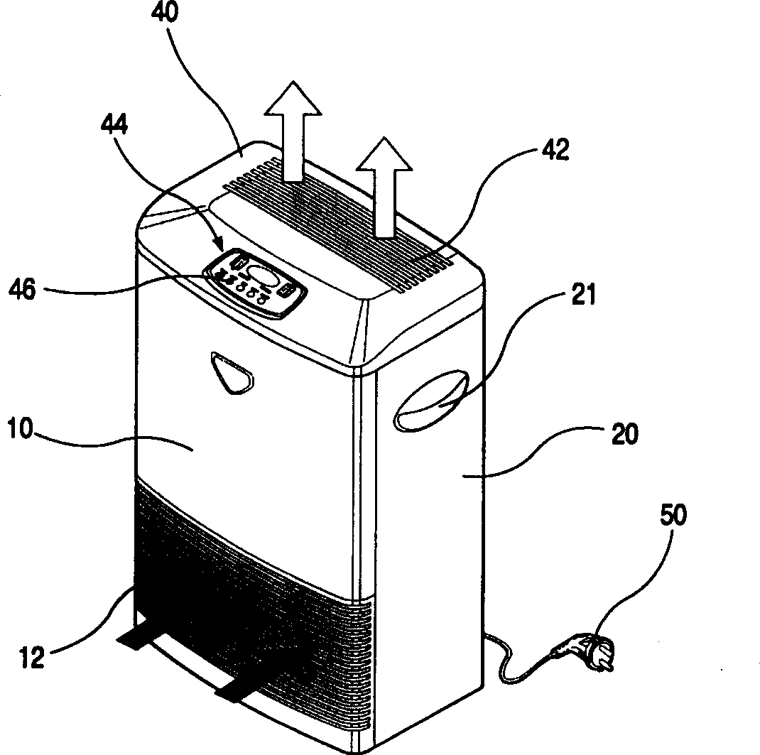
Since the outside air is sucked in only through the suction grille 12 at the bottom of the front panel 10 and discharged upward, it is difficult to circulate the air smoothly

Method used


Image

  • Air purifier
  • Air purifier
  • Air purifier

Examples


Embodiment Construction

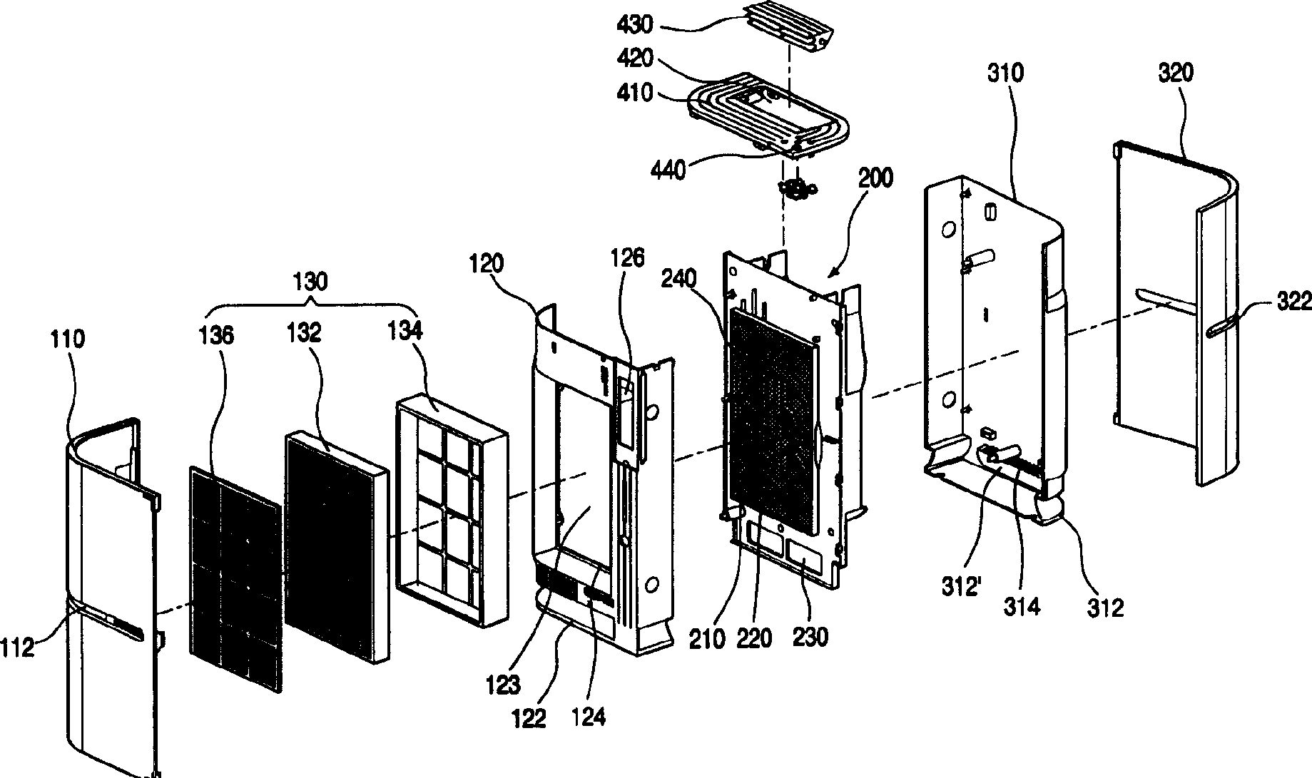
[0047] Hereinafter, the air cleaner of the present invention will be described in detail with reference to the accompanying drawings.

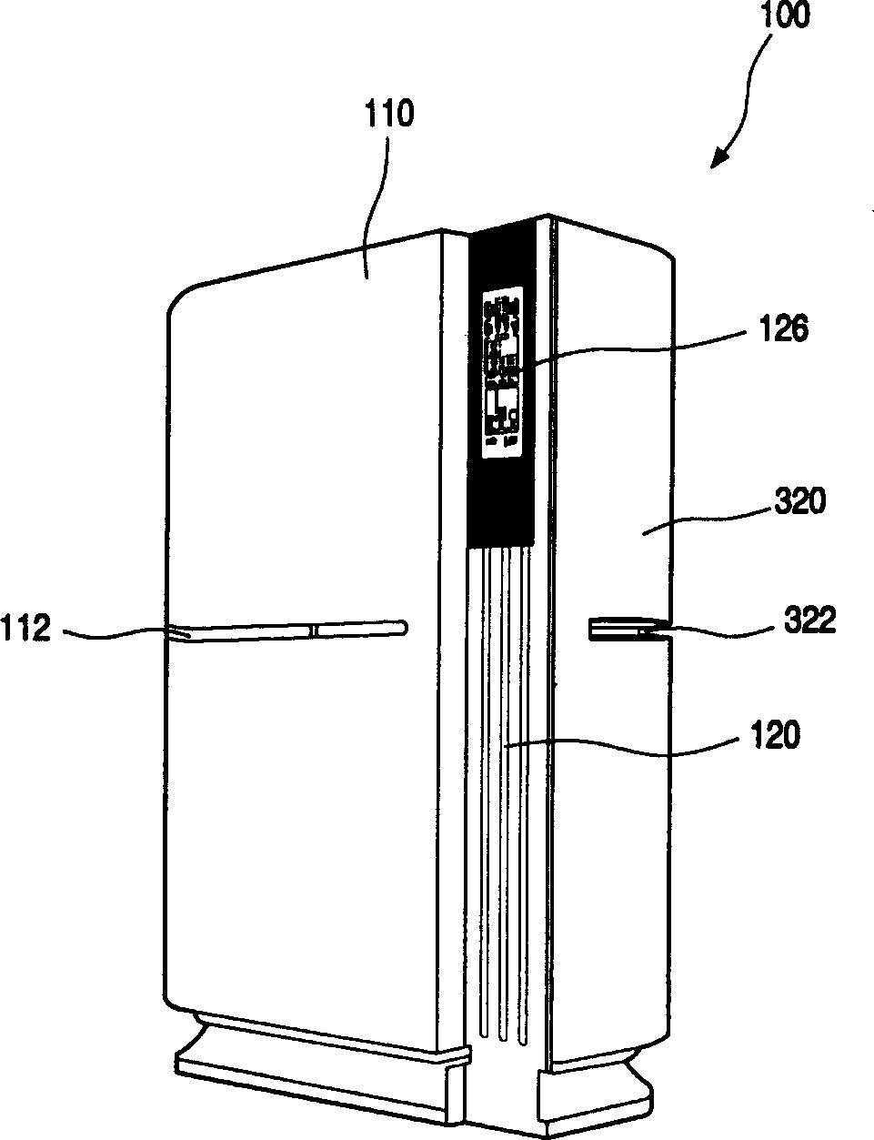
[0048] figure 2 It is a schematic diagram of the appearance of an air purifier embodiment of the present invention. As shown, the front and left side exteriors of the air cleaner 100 are formed by the front panel 110 . That is, the front panel 110 has an "L" shape and covers the front and left sides when viewed from above.

[0049] The front panel 110 is formed with a main suction port 112 . The main suction port 112 is formed through the central portion of the front panel 110 in the vertical direction, and has a length in the left-right direction. The main suction port 112 is also formed in communication with the left side of the front panel 110 . Therefore, outside air flows into the inside of the air cleaner 100 from the front and side through the above-mentioned main suction port 112 .

[0050] A front frame 120 is disposed behind th...


PUM


Abstract

The invention relates to a kind of air clarifier, which set all kinds of components on front frame forming the first half part of framework. The invention includes: front frame which forms the first half of framework; rear frame which forms the second half of framework; front face board which is setting on the said front frame and forms front face and one side face appearance. There are filter strainer apparatus which can filter inbreathed air; dust sensor which can detect air dustiness; gas sensor which can detect all kinds of gas content of air. There is also display window at the front side of the said front frame, which can reveal operating mode of air clarifier and air polluting degree. There is ozone generating apparatus at the offside of front frame, which can generate ozone and spray to air.

Description

technical field [0001] The present invention relates to an air cleaner (Air cleaner); more specifically, the air cleaner of the present invention is provided with various components on the front frame forming the front half skeleton, filters foreign matter, and displays after detecting the pollution degree of the air the pollution degree mentioned above. Background technique [0002] An air purifier is a device that purifies polluted air into fresh air. figure 1 It is a schematic diagram of an ordinary air purifier of conventional technology. [0003] As shown in the figure, the overall appearance of the air cleaner is formed by a front panel 10 , a housing 20 and a top panel 40 . The front panel 10 forms the front appearance, the housing 20 forms the side, back, and bottom appearances, and the top panel 40 forms the top appearance. [0004] On the lower half of the above-mentioned front panel 10, a suction window grid 12 is detachably arranged, and the suction window gri...

Claims


Application Information

Patent Timeline
IPC IPC(8): F24F3/16F24F13/28F24F11/02
Inventor 具南石
Owner LG ELECTRONICS (TIANJIN) APPLIANCES CO LTD
Learn More