
Electric incandescent lamp

A technology for incandescent lamps and incandescent filaments, which can be used in incandescent lamps, discharge lamps, circuits, etc., and can solve problems such as the inability to resist vibration of incandescent lamps

Inactive Publication Date: 2006-03-01
PATENT TREUHAND GESELLSCHAFT FUER ELECTRIC GLUEHLAMPEN M B H
View PDF1 Cites 3 Cited by
  • Summary
  • Abstract
  • Description
  • Claims
  • Application Information

AI Technical Summary

Problems solved by technology

An adequate vibration resistance of incandescent lamps for vehicle headlights cannot be achieved by means of such supports

Method used


Image

  • Electric incandescent lamp
  • Electric incandescent lamp

Examples


Embodiment Construction

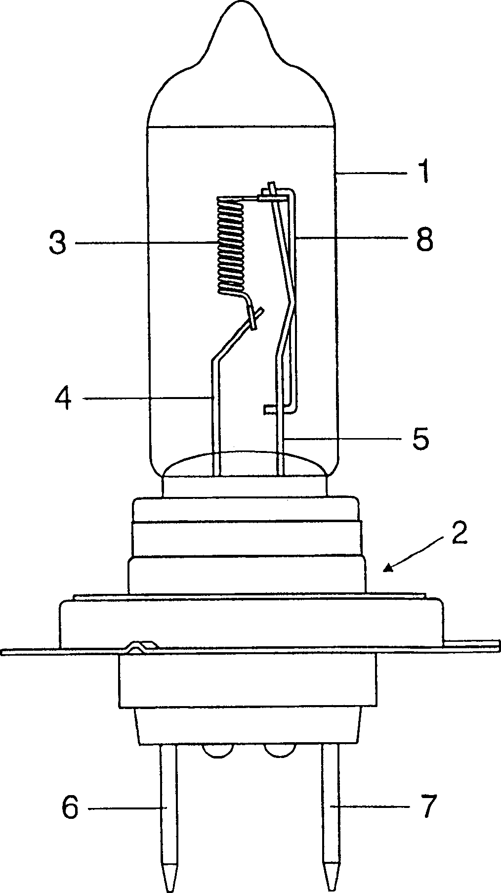
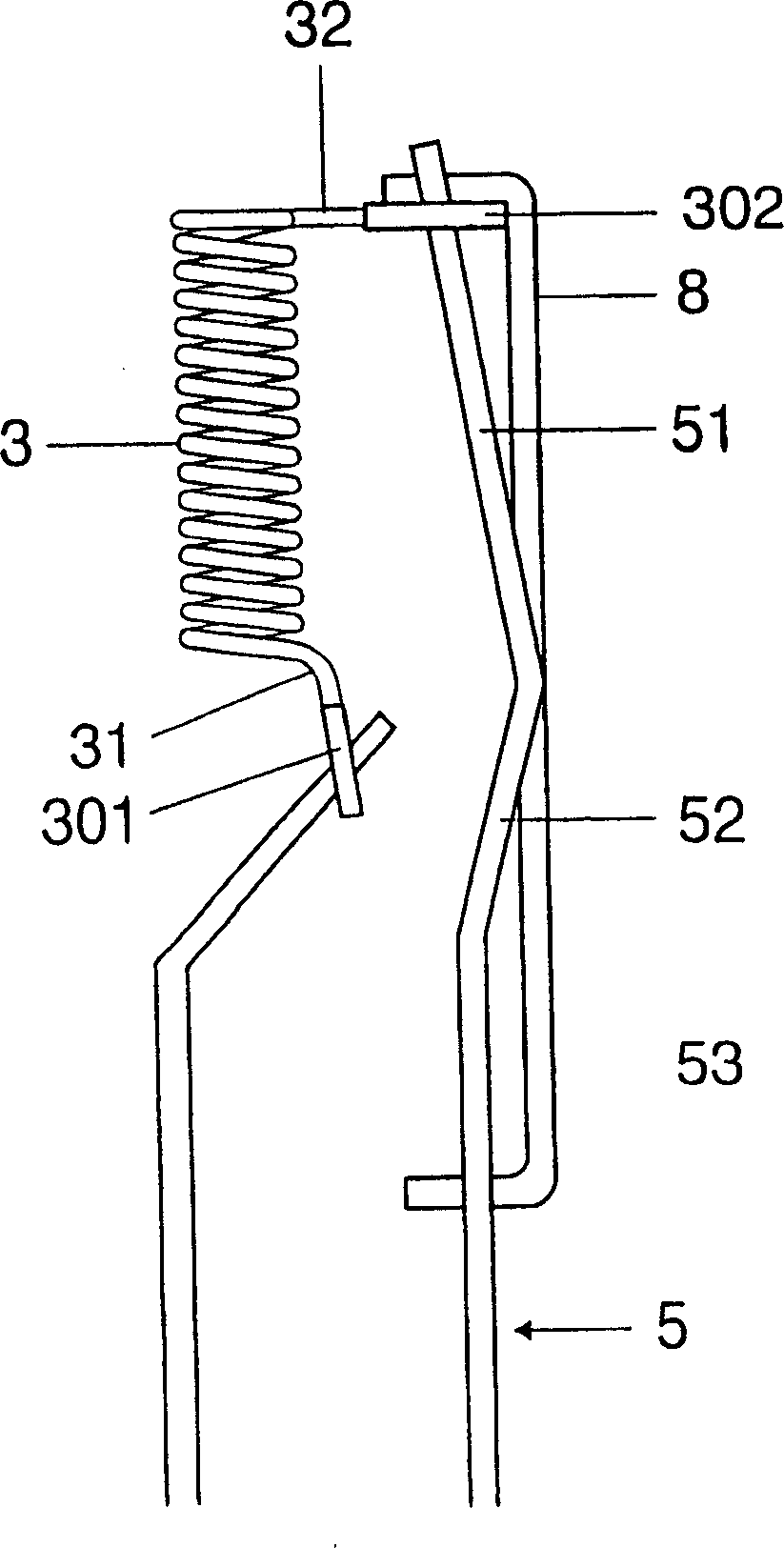
[0011] According to the present invention figure 1 The incandescent lamps shown are halogen lamps used in vehicle headlights, specifically H7 lamps. The lamp has a glass, substantially cylindrical lamp vessel 1 with a metal base 2 arranged at one end. An axial incandescent filament 3 is arranged in the lamp vessel 1 , and filament output wires 31 , 32 of the incandescent filament 3 covered with molybdenum tubes 301 , 302 are welded to power supply leads 4 , 5 respectively. The two power supply leads 4 , 5 are each connected in an electrically conductive manner to electrical connections 6 , 7 of the lampholder 2 . The power lead 5 connected to the filament output wire 32 remote from the lamp base is equipped with posts 8 welded to the power lead 5 at three points. The pillar 8 and the power supply wire 5 are designed as molybdenum wires with a thickness of 0.7mm. The strut 8 bridges the parts 51 , 52 , 53 of the bent power conductor 5 so as to stiffen the power conductor 5 ....


PUM


Abstract

The invention relates to an electric incandescent lamp, in particular a vehicle headlight lamp, having an incandescent filament(3), arranged inside a transparent lamp vessel(1), and supply leads for the incandescent filament, at least one of the supply leads(4,5) being provided with at least one reinforcing strut(8) in order to improve the vibration strength of the lamp.

Description

technical field [0001] The invention relates to an electric incandescent lamp according to the preamble of claim 1 . Background technique [0002] An electric incandescent lamp is disclosed, for example, in published application DE2105155. This text describes a halogen incandescent lamp for projection purposes, the incandescent filament of which is connected to a supply lead surrounded in each case by a support. One end of these supports is in each case embedded in the sealing end of the lamp vessel. The support body is designed as a coil. Such a support cannot achieve sufficient vibration resistance for incandescent lamps for vehicle headlights. Contents of the invention [0003] It is an object of the invention to provide an electric incandescent lamp with improved vibration resistance. [0004] This object is achieved according to the invention by the features of claim 1 . Obvious advantageous embodiments of the invention are p...

Claims


Application Information

Patent Timeline
Patent Type & Authority Applications(China)
IPC IPC(8): H01K1/40H01J5/34
CPCH01K1/40H01K1/18H01K7/02
Inventor F·奥尔C·塞希特尔
Owner PATENT TREUHAND GESELLSCHAFT FUER ELECTRIC GLUEHLAMPEN M B H
Learn More