
Screw device for high-adjusting a track span

A lead screw and track technology, which is used in tracks, track laying, track maintenance, etc., can solve the problems of track tipping, vertical screw tipping, etc., and achieve the effect of simple disassembly and simple horizontal adjustment device.

Inactive Publication Date: 2006-03-01
PCM RAIL ONE AG
View PDF1 Cites 11 Cited by
  • Summary
  • Abstract
  • Description
  • Claims
  • Application Information

AI Technical Summary

Problems solved by technology

[0003] Spindle arrangements have proven themselves well for the height adjustment of track groups, but up to now in principle two completely separate spindles were required for height adjustment and horizontal movement, and the horizontal adjustment spindle was in the In the case of large adjustment strokes there is a danger of the vertical spindle tipping over and thus the rail tipping over

Method used


Image

  • Screw device for high-adjusting a track span
  • Screw device for high-adjusting a track span
  • Screw device for high-adjusting a track span

Examples


Embodiment Construction

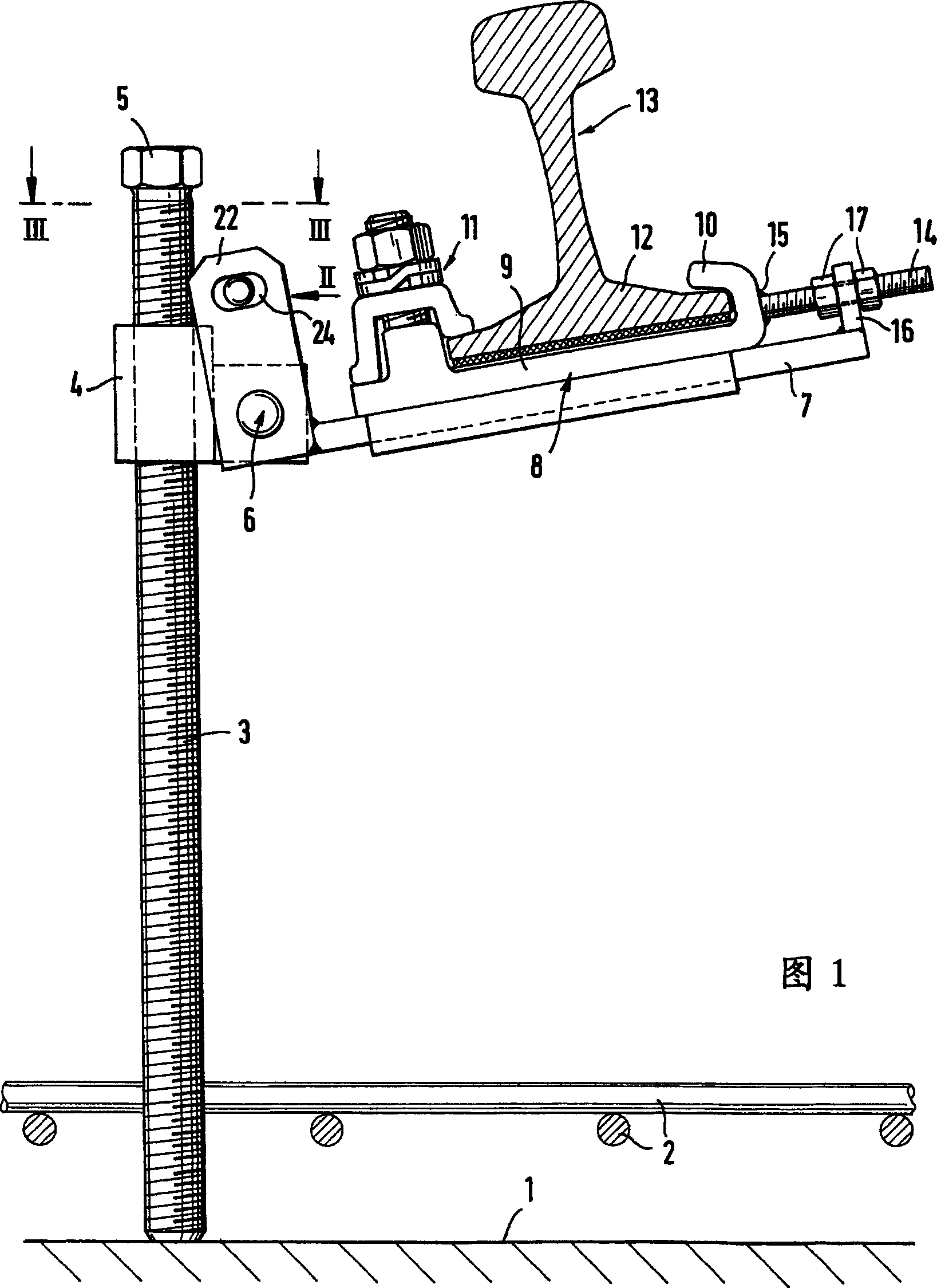
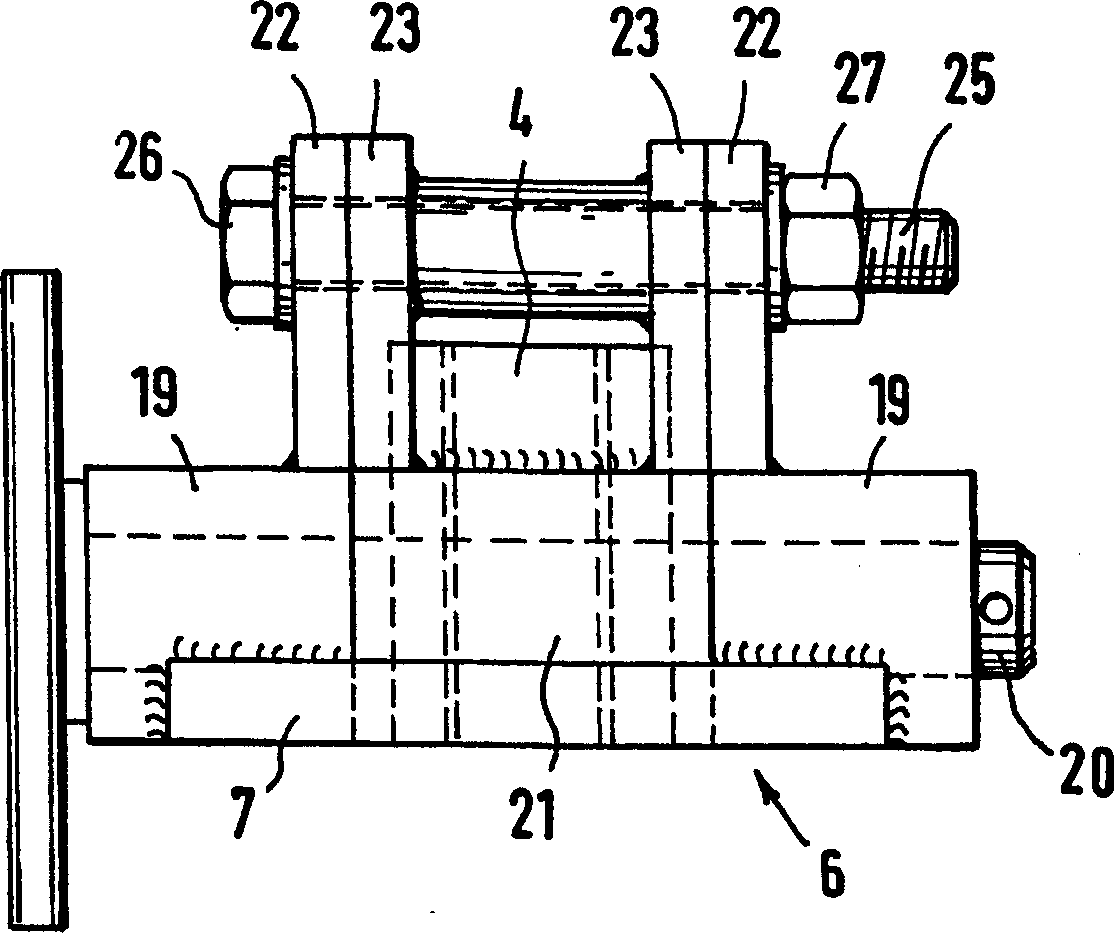
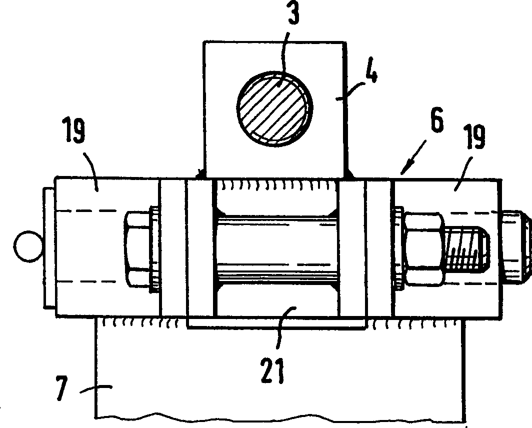
[0024] In FIG. 1 the upper side of the track substructure 1 can be seen, on which reinforcing steel bars 2 can be seen, which are embedded together in the subsequent pouring structure. Mounted on the substructure 1 is a height-adjusting spindle 3 , on which an elongated nut 4 is guided. The height of the elongated nut can be adjusted by turning the screw, for example via its hexagonal head 5 , to which a horizontal screw plate 7 is fixed by means of an articulation 6 . A slide 8 is mounted on said horizontal screw plate in a transversely slidable manner, said slide comprising a rib 9 with a clamping hook 10 and a conventional rail for fixing the rail base 12 of a rail 13 Bottom screw clamp 11. The rails 13 are here rails of a rail block with not shown sleepers connecting the rails, wherein the screw arrangements according to the invention are arranged at intervals along one or the other rail. A leveling screw 14 is used to level the track group, said leveling screw is fasten...


PUM


Abstract

The invention relates to a screw device for high-adjusting and a snaping to track on a lower structure, having a transverse cantilever on a guided long nut with an adjustable height acting on the rail from beneath and fixed on a height regulating screw. The transverse cantilever is designed to be a horizontal screw plate beard on the long nut and swung around a horizontal axes. A slide block with a clamping holding device for rail base is able to move on the horizontal screw plate transversely to the high-adjusting screw recurring to the first and second screw apparatus.

Description

technical field [0001] The present invention relates to a screw assembly for height adjustment and alignment adjustment of rails on a substructure, which has a height adjustable screw / mandrel acting on the rail from below and fixed on a height adjustment screw / spindle A transverse cantilever beam on a ground-guided elongated nut. Background technique [0002] When height-adjusting and aligning track units / track units (Gleisrost) for fixed carriageways, it is not only always necessary to adjust the rails to the correct height, but it is also necessary to be able to provide a certain superelevation at bends (berhohung), for which the track combination must be tiltable. Therefore, in a device known from DE 197 39 671 C2 for height adjustment and temporary support of rails, the rails are supported on a support edge (Lagerschneide), so that when one side of the rail combination is raised On the other side, as is the case in bends, the rails are correspondingly pivotable on the...

Claims


Application Information

Patent Timeline
IPC IPC(8): E01B29/40E01B1/00
CPCE01B2204/06E01B1/004E01B29/40E01B29/04
Inventor H-P・维尔茨A・皮埃里恩格
Owner PCM RAIL ONE AG
Learn More