
Multi-pole connector

A multi-pole connector and connector technology, applied in the direction of connection, two-part connection device, parts of the connection device, etc., can solve the problem that the terminal unit 102 cannot change the distance between the contacts 103, the power terminal is damaged, and the plug connector is inserted. Problems such as increased pulling force, to achieve the effect of implementing product management, easy core count expansion, and easy product management

Inactive Publication Date: 2006-03-08
HIROSE ELECTRIC GROUP
View PDF2 Cites 11 Cited by
  • Summary
  • Abstract
  • Description
  • Claims
  • Application Information

AI Technical Summary

Problems solved by technology

[0015] However, when the former multi-pole connector is used as the female and male side connectors, the power terminals are exposed before they are assembled into the housing for power terminals. In this state, the power terminals may be damaged, and the power terminals are directly held. In the power terminal holding part of the housing part for the power terminal, the signal terminal is held directly in the signal terminal holding part of the housing part for the signal terminal, and, in the male-side connector, the power terminal is held directly in the housing part for the power terminal. The power terminal holding part and the signal terminal are directly held on the signal terminal holding part of the signal terminal housing part, so in the female side and male side connectors, the distance between the power terminal housing part and the signal terminal housing part cannot be changed to connect the contact terminals It is held in the terminal holding part, so it is not possible to select the type of terminal unit while sharing the connector housing
[0016] When the aforementioned latter multi-pole connector is used, since the contact of the male terminal forms a pin-shaped columnar contact 112 relative to the contact 103 of the female terminal, the plugging force of the plug connector 100 increases. , can not achieve high connector life
[0017] In addition, although the terminal unit 102 is inserted into the connector housing 101, the pitch of the terminal unit 102 cannot be changed to mount the contacts 103, so the type of terminal unit cannot be selected while sharing the connector housing.

Method used


Image

  • Multi-pole connector
  • Multi-pole connector
  • Multi-pole connector

Examples


Embodiment Construction

[0069] Hereinafter, embodiments of the present invention will be described with reference to the drawings.

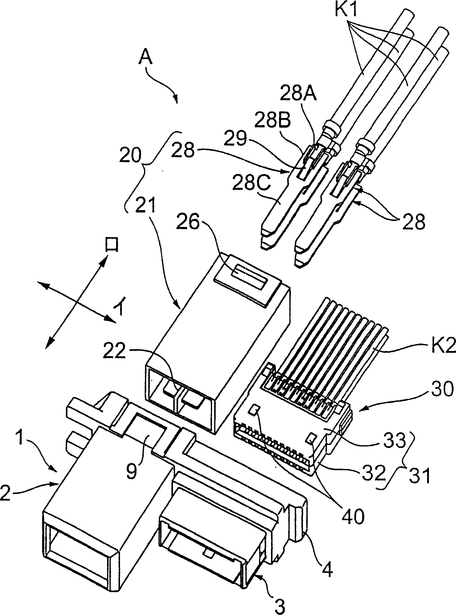
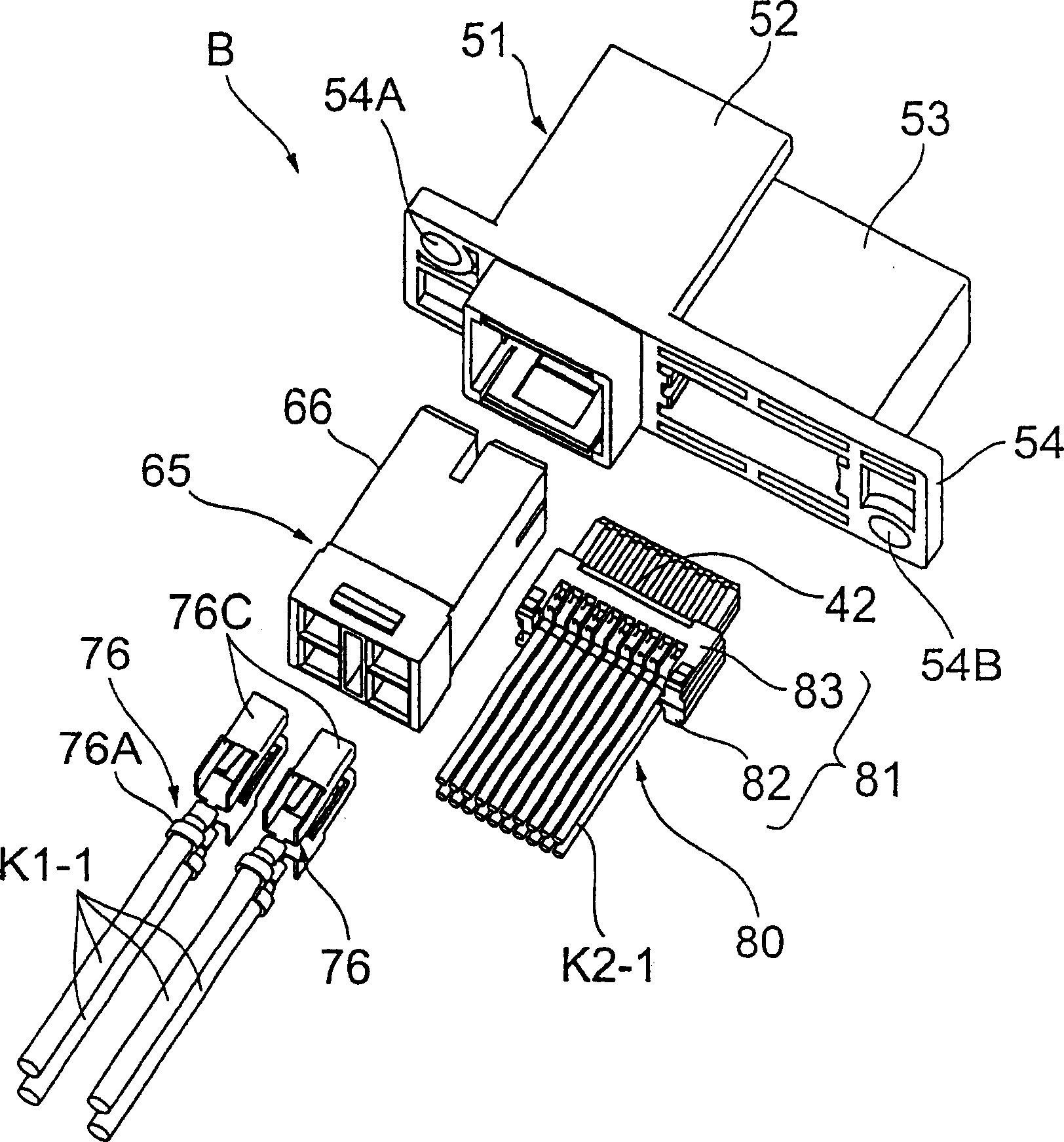
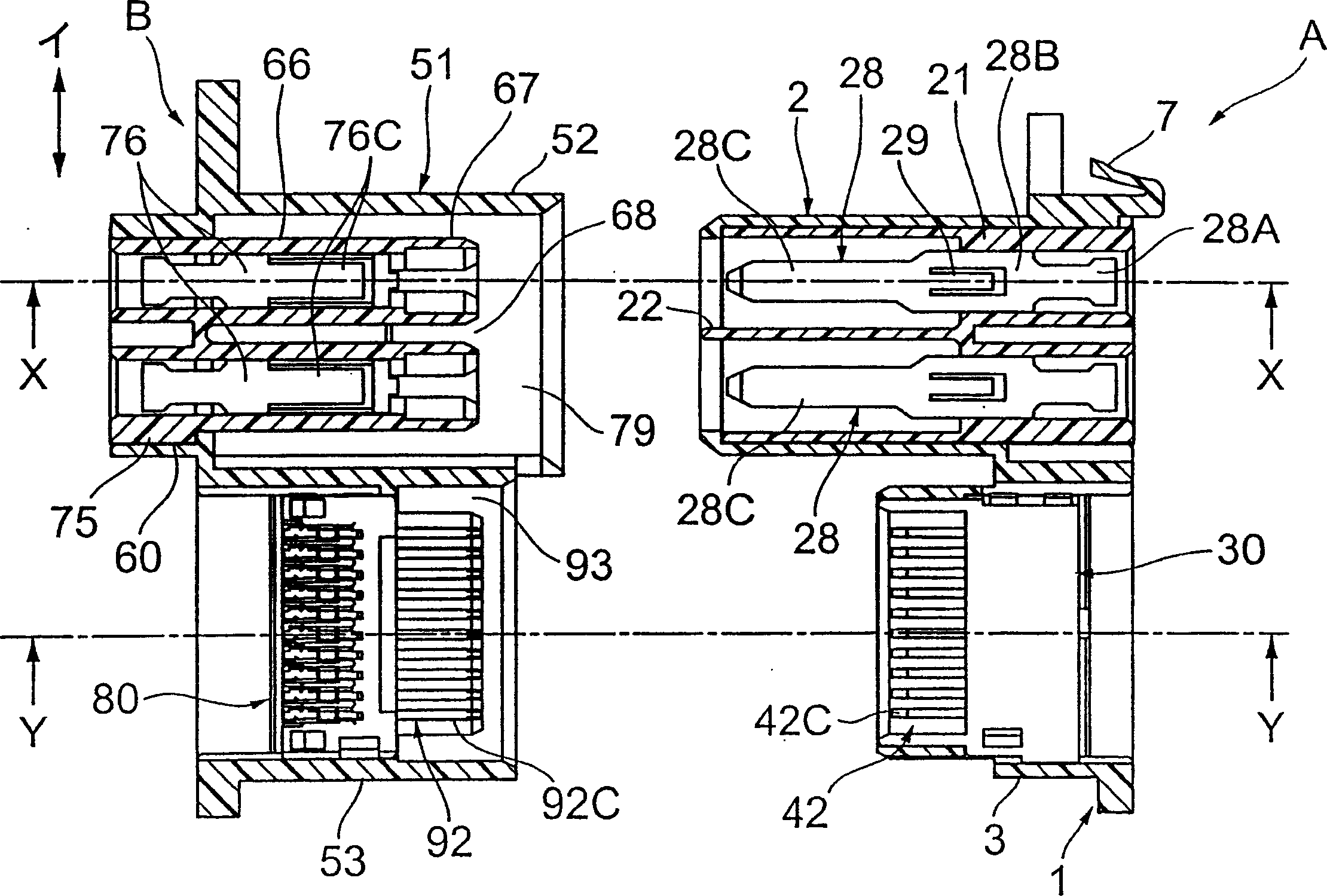
[0070] figure 1 It is a perspective view of the plug connector of the multi-pole connector of the embodiment of the present invention. figure 2 It is a perspective view of the receptacle connector of the multi-pole connector of the embodiment of the present invention. image 3 This is a cross-sectional view of the plug connector and receptacle connector before mating. Figure 4 yes image 3 The X-X section view. Figure 5 yes image 3 The X-X section view.

[0071] The multi-pole connector of the present invention has a plug connector A as a connector and a receptacle connector B that is a counterpart connector coupled to the connector A. As shown in FIG.

[0072] Plug connector A such as figure 1 As shown, there are a connector housing 1 , a power supply terminal unit (terminal unit) 20 , and a signal terminal unit (terminal unit) 30 .

[0073] like figure...


PUM


Abstract

To provide a multipolar connector allowing the number of conductors to be easily expanded and allowing its service life to be extended.Signal terminals 42 (mating signal terminals 92) are mounted to terminal mounting parts 45 (88) with one-side case part 32 (82) and the other-side case part 33 (83) expanded. Each signal terminal 42 is bent in a V-shaped form in profile; its bending point has a contact part 42C used as a contacting part 43; a bellows contact (that is, a contact made by bending a thin plate into a shape so as to obtain a uniform spring characteristic) is used for the signal terminal (female terminal) 42 as each mating signal terminal 92 has a flat linear mating contact part 92C; and the mating signal contact (male terminal) 92 uses the flat linear contact.

Description

technical field [0001] The present invention relates to electrical connectors, and more particularly to multi-pole connectors provided with movable floating connectors or the like for a mounting plate. Background technique [0002] Generally, a floating connector is known as a connector used for connecting slidable devices inside a copier or the like. [0003] The floating connector is formed as a pair of a male-side connector and a female-side connector, and the male-side connector can be fitted with the female-side connector. Usually, either one of the connectors is provided so as to be movable relative to the mounting plate, and a fitting error when the male-side connector and the female-side connector are mated can be absorbed. [0004] A conventional multi-pole connector of this type is described in Japanese Patent Document 1. The female-side connector in the multi-pole connector has: a housing portion for power terminals, and a housing portion arranged side by side at...

Claims


Application Information

Patent Timeline
Patent Type & Authority Applications(China)
IPC IPC(8): H01R13/46H01R13/518H01R13/40H01R13/05H01R13/11H01R13/64H01R24/00
Inventor 松崎修一龟谷武彦
Owner HIROSE ELECTRIC GROUP
Learn More