Telescopic shaft for motor vehicle steering

A telescopic shaft and steering shaft technology, which is applied to the steering column, steering control mounted on the vehicle, steering control, etc., can solve the problems of torque reduction, affecting the long life of the steering shaft, and inability to obtain hysteresis. High-rigidity feel steering characteristics, prevent excessive hysteresis, and ensure the effect of deflection

Inactive Publication Date: 2006-03-15
NSK LTD +1
View PDF1 Cites 32 Cited by
  • Summary
  • Abstract
  • Description
  • Claims
  • Application Information

AI Technical Summary

Problems solved by technology

Therefore, it is difficult to maintain the preload performance for a long time, and it may also affect the longevity of the steering shaft
[0015] Third, when the torque is transmitted, the leaf spring may slide laterally (sideways) from the axial groove in the circumferential direction, resulting in a reduction in the transmitted torque
Therefore, not only the linear torsional performance required by the steering shaft cannot be obtained, but also the proper hysteresis cannot be obtained

Method used


Image

  • Telescopic shaft for motor vehicle steering
  • Telescopic shaft for motor vehicle steering
  • Telescopic shaft for motor vehicle steering

Examples


no. 1 Embodiment

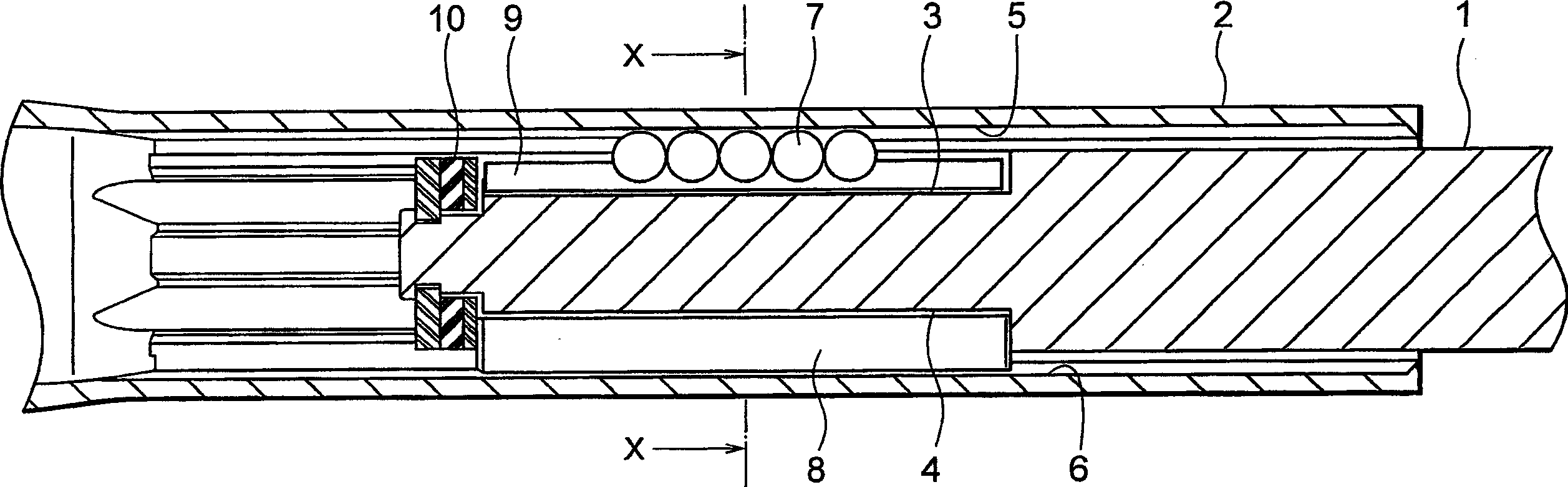
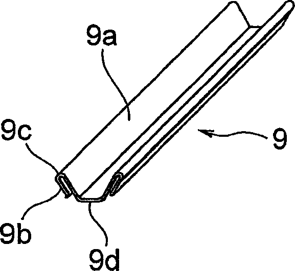
[0072] Figure 2A It is a longitudinal sectional view of a vehicle steering telescopic shaft according to a first embodiment of the present invention, Figure 2B is a perspective view of a leaf spring used as an elastomer / component. image 3 is along Figure 2A A cross-sectional view taken along the line X-X.

[0073] Such as Figure 2A As shown, the telescopic shaft for vehicle steering (hereinafter referred to as the telescopic shaft) includes a male shaft 1 and a female shaft 2 that cannot rotate with each other but are slidably engaged with each other.

[0074] Such as image 3 As shown, three grooves 3 extending in the axial direction are provided on the outer peripheral surface of the male shaft 1 at equal intervals of 120 degrees in the circumferential direction. Correspondingly, three axially extending grooves (hereinafter referred to as axial grooves) 5 are provided on the inner peripheral surface of the female shaft 2 at equal intervals of 120 degrees in the cir...

no. 2 Embodiment

[0147] Figure 8 is a cross-sectional view showing a vehicle steering telescopic shaft according to a second embodiment of the present invention (corresponding to the Figure 2A Cross-sectional view taken along the line X-X).

[0148] The second embodiment is basically the same as the first embodiment described above, in that the bottom surface 3b of the axial groove 3 is separated from the bottom 9d of the leaf spring 9 by a predetermined distance.

[0149] Therefore, in this case, as described above, the hysteresis can be controlled without friction when the axial groove 3 and the leaf spring 9 move relative to each other, so that the hysteresis can be set to be small.

no. 3 Embodiment

[0151] Figure 9 is a cross-sectional view showing a vehicle steering telescopic shaft according to a third embodiment of the present invention (corresponding to the Figure 2A Cross-sectional view taken along the line X-X).

[0152] The third embodiment is basically the same as the above-mentioned second embodiment, wherein, in the leaf spring 9, the ball-side contact portion 9a is formed at the end of the bent portion of the leaf spring 9, and the contact portion 9b is formed at the end of the leaf spring 9. The middle part of the bent part.

[0153] Also in the same manner as in the second embodiment described above, the bottom surface 3b of the axial groove 3 is separated from the bottom 9d of the leaf spring 9 by a predetermined distance.


PUM


Abstract

In a telescopic shaft for vehicle steering which is installed in a steering shaft of a vehicle and in which a male shaft and a female shaft are fitted to each other to be unrotatable and freely slidable, a spherical member (7) is interposed between at least one of axial grooves (3, 5) which are respectively formed on the outer peripheral surface of the male shaft (1) and on the inner peripheral surface of the female shaft (2) through an elastic member (9), and a columnar member (8) is interposed between at least another of axial grooves (4, 6) which are respectively formed on the outer peripheral surface of the male shaft (1) and on the inner peripheral surface of the female shaft (2). The elastic member (9) comprises a contact portion (9a) on the spherical member side which is in contact with the spherical member, a contact portion (9b) on the groove surface side which is separated from the contact portion (9a) on the spherical member side by a predetermine distance in a substantially circumferential direction and, at the same time, in contact with the groove surface of the axial groove of the male shaft or the female shaft, and a biasing portion (9c) for elastically biasing the contact portion on the spherical member side and the contact portion on the groove surface side in a direction in which both the contact portions are separated from each other.

Description

technical field [0001] The present invention relates to a telescoping shaft for vehicle steering which is installed in the steering shaft of a vehicle, and a male shaft and a female shaft cannot rotate with each other but are slidably fitted with each other. Background technique [0002] The telescopic shaft of the vehicle steering mechanism needs to have the ability to absorb the axial displacement generated when the vehicle is running and prevent such displacement or vibration from being transmitted to the steering wheel. In addition, the telescopic shaft also needs to have the function of moving and adjusting the position of the steering wheel in the axial direction, so as to obtain the best position for the driver to drive the vehicle. [0003] In any of the above cases, the telescoping shaft needs to reduce rattling noise, reduce the play feeling of the steering wheel, and reduce sliding resistance during sliding operation in the axial direction. [0004] Therefore, tr...

Claims


Application Information

Patent Timeline
Patent Type & Authority Applications(China)
IPC IPC(8): B62D1/20F16D3/06B62D1/16B62D1/185F16C3/035F16C25/08F16C27/06F16C29/00F16C29/04F16C29/12F16C33/58F16C33/62
CPCB62D1/185F16D3/06B62D1/20F16C33/58F16C3/035B62D1/16F16D3/065F16C2326/24F16C33/62F16C29/04F16C29/123F16C29/002F16C29/007
Inventor 汤川谨次山田康久
Owner NSK LTD
Why Eureka
Try Eureka