Cloth feeding device for sewing machine

A technology of a cloth feeding device and a sewing machine, which is applied in the direction of sewing machine components, cloth feeding mechanisms, sewing equipment, etc., and can solve problems such as inability to correctly transport the sewn object and the error of the cloth feeding amount, so as to save setting space, suppress jumping, The effect of reducing the number of parts

Active Publication Date: 2006-03-29
JUKI CORP
View PDF7 Cites 7 Cited by
  • Summary
  • Abstract
  • Description
  • Claims
  • Application Information

AI Technical Summary

Problems solved by technology

[0012] When the feed dog 105 exerts an upward movement force on such a presser foot 107 with a large displacement on the downstream side of the cloth feeding direction, the elastically pressed and supported presser foot 107 jumps upward, and the sewing object cannot be conveyed correctly.
[0013] In addition, if this phenomenon is suppressed, such as Figure 7 As shown, if the heights of the protrusions from the needle plate are adjusted to be the same at the upstream end and the downstream end of the feed dog 105, then on the upstream side where the vertical displacement is small, the position of the vertex on the major axis side of the oblong circle appears at Above the needle plate, it is possible to return to the feeding direction Figure 7 The problem of the distance of the symbol h
As a result, the cloth feed amount error occurs at the upstream side end and the downstream side end of the feed dog, and at this time, the discomfort that the sewing object cannot be fed correctly also occurs.

Method used


Image

  • Cloth feeding device for sewing machine
  • Cloth feeding device for sewing machine
  • Cloth feeding device for sewing machine

Examples


no. 1 example

[0050] (overall structure of the embodiment of the present invention)

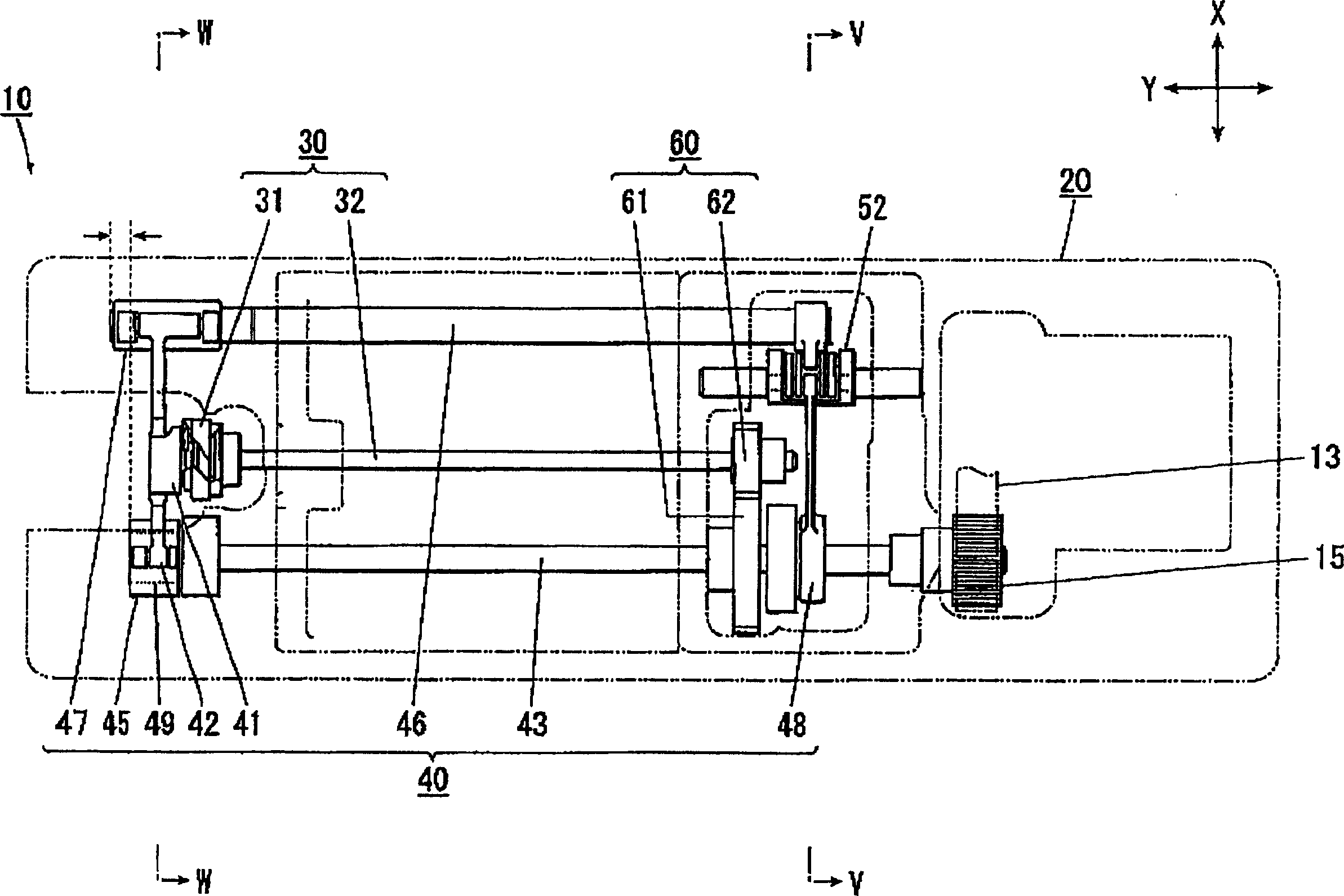
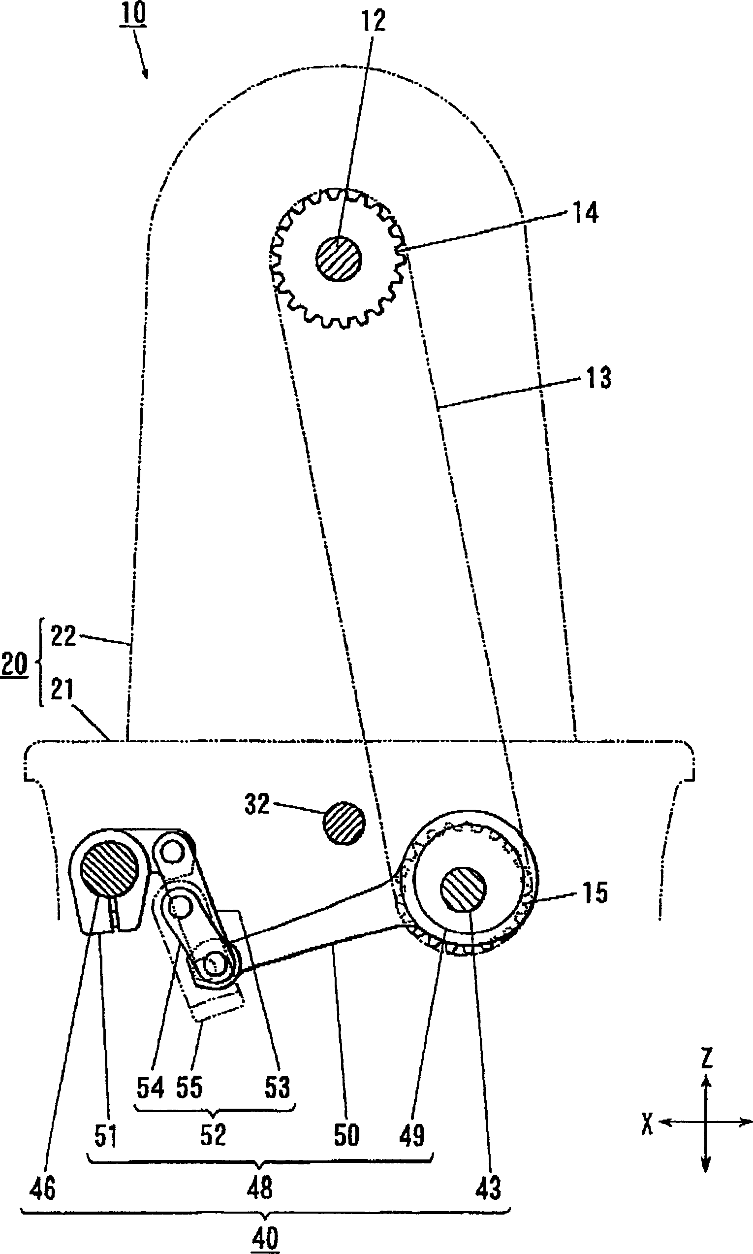
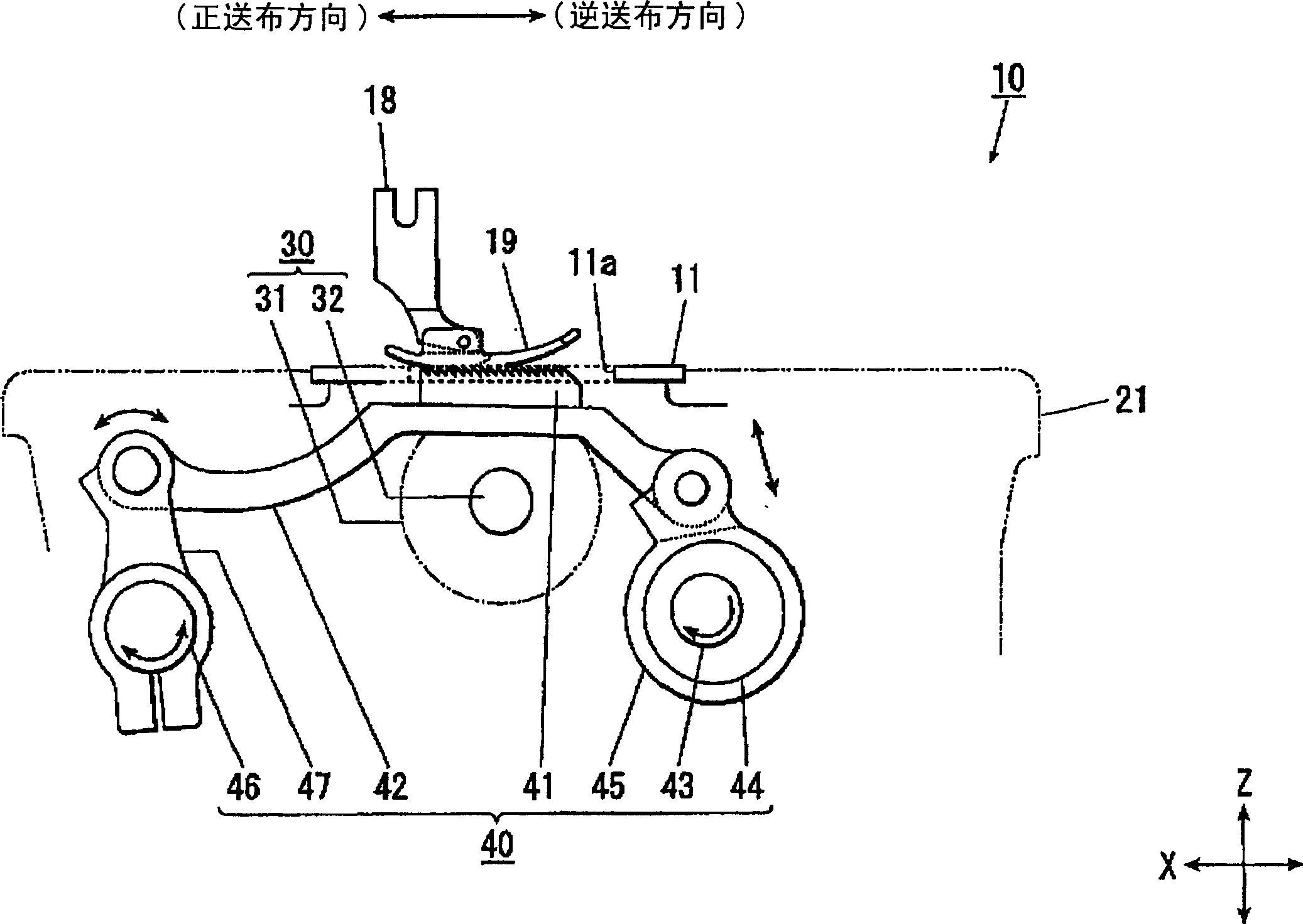
[0051] Below, refer to Figure 1 to Figure 5 Embodiments of the present invention will be described in detail. figure 1 It is a structural diagram of only the main structure of the sewing machine 10 according to the embodiment of the present invention, which will be described later in the bottom plate portion 21. figure 2 yes figure 1 The cross-sectional view along the line V-V in, image 3 yes figure 1 A cross-sectional view along the line W-W in .

[0052] The above-mentioned sewing machine 10 has: an unillustrated vertical movement mechanism for moving the machine needle up and down, an unillustrated sewing machine motor as its driving source, and a suture thread that winds the bobbin thread around the suture thread passing through the machine needle through the full rotary hook 31. The rotary hook mechanism 30 in the middle, the cloth feeding device 40 that is consistent with the up and down m...

no. 2 example

[0110] Next, a second embodiment of the present invention will be described. In addition, in this embodiment, the same symbols are used for the same structures as those of the above-mentioned first embodiment, and repeated description thereof will be omitted.

[0111] On the sewing machine 100 of this embodiment, the difference from the above-mentioned sewing machine 10 is that the other end of the upper and lower cloth feeding shaft 430 with the pulley 15 installed at one end, and the front end, that is, the cloth feeding seat 420 of the upper and lower cloth feeding shaft 430 The end portion on the side is located on the side of the vertical body 22 than the end portion on the opposite side of the vertical body 22 of the full rotary hook 31 (refer to Figure 9 ). which is, Figure 9 The shown upper and lower feed shaft 430, the end of the cloth feed seat 420 side, is located at Figure 9 on the right side of the full rotary hook 31 left end. In addition, the cloth feed s...


PUM


Abstract

The present invention provides a cloth feeding device of the sewing machine, having a cloth feeding holder of the cloth feed teeth for keeping the sewed object on the feeding needle board, an upper and lower cloth feeding axe for full rotation and bringing shock driving force upwards and downwards, a horizontal cloth feeding axe for bring shock driving force to the cloth feeding holder in the feeding direction, a regulating machine of the amount of the cloth for adjusting the horizontal shock amplitude of the horiaontal cloth feeding axe; moreover, the upper and lower cloth feeding axis are set on the upstream side of the feeding direction closer to the sewed object contrast to the horizontal cloth feed axis. Ends of the cloth feed base side of the upper and lower cloth feed axis are formed on the end of the cloth feed base side or the fully rotary hook closer to the vertical unit body side compared with the horizontal cloth feed axis. The cloth feed unit of the sewing machine can exactly transmit the sewed object.

Description

technical field [0001] The present invention relates to a cloth feeding device of a sewing machine which transfers a sewing object by using the cloth feeding movement of a cloth feeding dog. Background technique [0002] On the sewing machine, the driving force is transmitted from the sewing machine motor as the main driving source to each part to realize the simplification of the driving source. And, on the side of the sewing machine head, the driving force is applied to each part by the upper shaft fully rotated by the sewing machine motor in the sewing machine head; The lower shaft, which is fully rotated by the upper shaft at the same speed and in the same direction, exerts its driving force on the feeding teeth and other parts. [0003] The feed dog uses the upper and lower feed shafts and the horizontal feed shaft to combine and give vertical vibration and vibration in the feeding direction at the same cycle and in an appropriate phase, and to draw an elongated circul...

Claims


Application Information

Patent Timeline
Patent Type & Authority Applications(China)
IPC IPC(8): D05B27/02D05B27/22
CPCD05B27/02D05B27/00D05B27/04
Inventor 秋山辰仁武田育子佐佐木义行岩田寿之
Owner JUKI CORP
Why Eureka
Try Eureka