Method and device for flaw detection of magnetic powder

A technology of magnetic particle inspection and magnetization device, applied in the direction of material magnetic variables, can solve problems such as difficult inspection defects, and achieve the effect of high-precision magnetic particle inspection

Inactive Publication Date: 2006-03-29
NIPPON STEEL CORP
View PDF0 Cites 10 Cited by
  • Summary
  • Abstract
  • Description
  • Claims
  • Application Information

AI Technical Summary

Problems solved by technology

On the other hand, if the defect extends in the same direction as the magnetization direction

Method used


Image

  • Method and device for flaw detection of magnetic powder
  • Method and device for flaw detection of magnetic powder
  • Method and device for flaw detection of magnetic powder

Examples


no. 1 approach

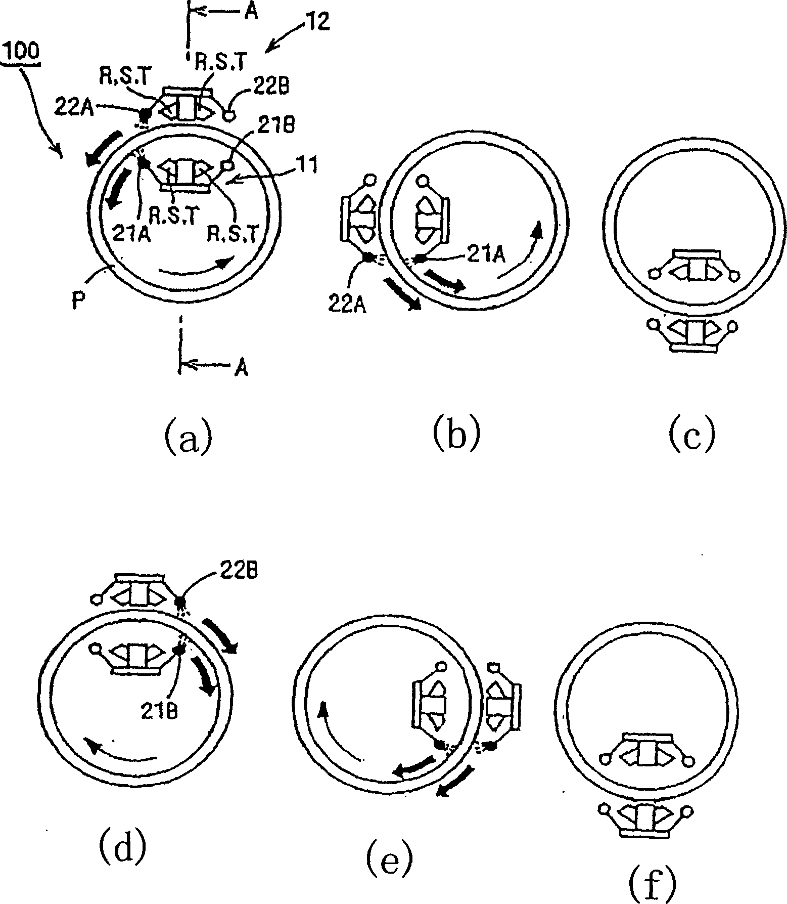
[0049] Hereinafter, the best mode for carrying out the magnetic particle inspection method and the magnetic particle inspection apparatus of the present invention will be described with reference to the drawings. In addition, in the description of each of the following embodiments, the object to be inspected is a steel pipe, and a case where magnetic particle inspection is performed on the inner surface and the outer surface of the steel pipe as inspection objects is taken as an example. However, the present invention is not limited to this form, and it can be used other than steel pipes as long as it is a tubular object made of a ferromagnetic material. In addition, it goes without saying that it can be used even if the inspection surface is only either the inner surface or the outer surface of the object to be inspected.

[0050] figure 1 (a)~ figure 1 (f) is explanatory drawing which shows the state of the magnetic particle flaw detection of the inner surface and the oute...

no. 2 approach

[0079] Next, a second embodiment will be described. In addition, in the description of each of the following embodiments, parts different from those of the first embodiment will be described, and the same parts will be given the same symbols in the drawings to appropriately omit overlapping descriptions.

[0080] Figure 4 (a)~ Figure 4 (f) is explanatory drawing which shows the state of the magnetic particle flaw detection of the inner surface and the outer surface of the steel pipe P using the magnetic particle flaw detection apparatus 100-1 which concerns on this embodiment with time. The main difference between this magnetic particle testing device 100 - 1 and the magnetic particle testing device 100 of the first embodiment is that a spreading device 23 is provided on the magnetizing device 11 and a spreading device 24 is provided on the magnetizing device 12 .

[0081] That is, on the magnetizing device 11, it is provided that the distributing device 23 can be switched...

no. 3 approach

[0095] Next, a third embodiment will be described.

[0096] Figure 5 (a)~ Figure 5 (f) is explanatory drawing which shows the state of the magnetic particle flaw detection of the inner surface and the outer surface of the steel pipe P using the magnetic particle flaw detection apparatus 100-2 of this embodiment with time. The main difference between this magnetic particle flaw detection apparatus 100-2 and the magnetic particle flaw detection apparatus 100-1 of the second embodiment is that the spreading device configuration switching devices 25 and 26 are not provided, so the spreading device 23 provided on the magnetizing device 11 and the The spreading means 24 provided on the magnetizing means 12 are all arranged in fixed positions.

[0097] Next, the state of performing the magnetic particle flaw detection will be described based on the magnetic particle flaw detection apparatus 100-2 of the present embodiment having the above configuration.

[0098] Firstly, when th...


PUM


Abstract

To provide a method and a system for magnetic particle inspection which can achieve high-precision magnetic particle inspection by forming clearer magnetic particle patterns. This magnetic particle inspection system 100 is equipped with magnetizing equipment 11, 12 which allows rotating magnetic field to act on surface P of horizontally-arranged tubular test material, nozzle actuators 21A, 21B, 22A, 22B for sprinkling magnetic powder liquid on surface of the test material, and a driving mechanism 3 which allows these magnetizing equipment and nozzle actuators to be rotated integrally about the central axis of the test material along its circumferential direction. The nozzle actuators are respectively provided on both ends in the traveling direction of the magnetizing equipment, to sprinkle magnetic powder liquid from the nozzle actuators mounted on the end of the same directional side as the magnetic powder flowing direction; while the driving mechanism moves the magnetizing equipment toward the same direction as the sprinkled magnetic powder flowing direction so that traveling speed of the magnetizing equipment is nearly equal to the flowrate of the magnetic powder liquid immediately, after being sprinkled.

Description

technical field [0001] The invention relates to a magnetic particle flaw detection method and a magnetic particle flaw detection device. In particular, the present invention relates to a magnetic particle inspection method and a magnetic particle inspection apparatus capable of performing high-precision magnetic particle inspection by forming a clear magnetic particle pattern even on a tubular object to be inspected such as a so-called steel pipe. Background technique [0002] Magnetic particle testing (magnetic particle testing) is known as a non-destructive testing method for checking minute defects existing on the surface of a magnetic body and its vicinity. This magnetic particle flaw detection utilizes such a technique that if the object to be inspected composed of a magnetic body is magnetized, when there is a defect that blocks the magnetic force lines by extending (existing in an extended state) on the surface of the object to be inspected and its vicinity, when this...

Claims


Application Information

Patent Timeline
IPC IPC(8): G01N27/84
Inventor 石原昇大滝哲朗
Owner NIPPON STEEL CORP
Why Eureka
Try Eureka