Fuel jet valve

A fuel injection valve, fuel flow technology, applied in the direction of fuel injection device, special fuel injection device, charging system, etc., can solve the problems of expensive fuel injection valve, peeling off, expensive processing, etc. low cost effect

Inactive Publication Date: 2006-04-05
ROBERT BOSCH GMBH
View PDF1 Cites 8 Cited by
  • Summary
  • Abstract
  • Description
  • Claims
  • Application Information

AI Technical Summary

Problems solved by technology

[0006] However, these layers have the disadvantage that they are very expensive to manufacture and thus make the fuel injection valve considerably more expensive
Furthermore, even when this layer is applied correctly, there is the danger that this very hard and brittle material will flake off due to the strong mechanical stresses when the valve needle fits onto the valve seat

Method used


Image

  • Fuel jet valve
  • Fuel jet valve

Examples


Embodiment Construction

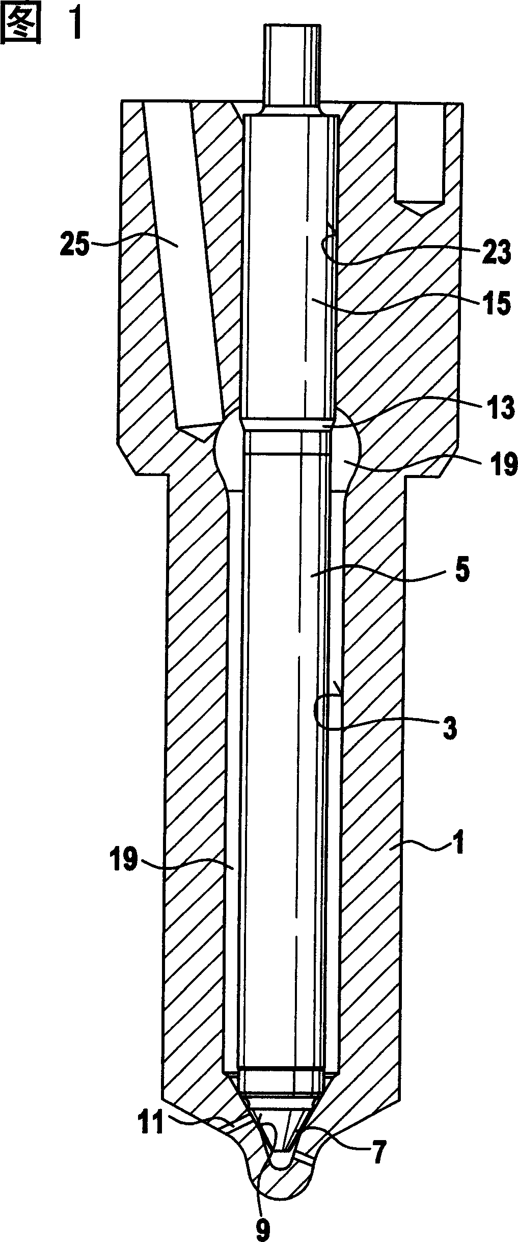
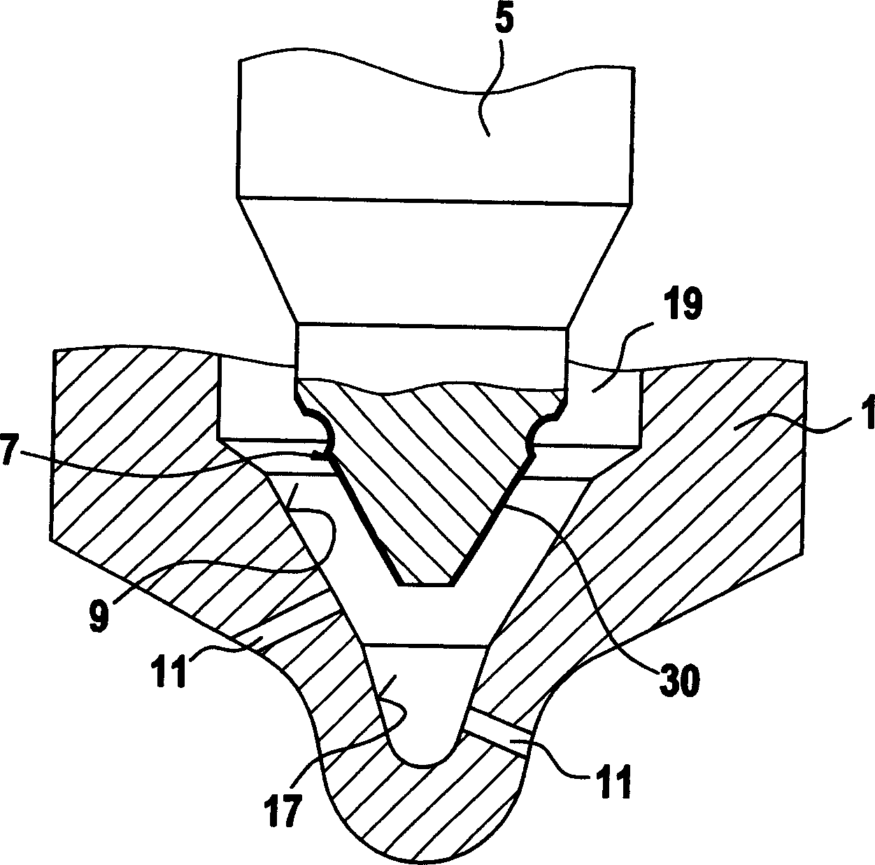
[0016] FIG. 1 shows a longitudinal section through a fuel injector according to the invention. A bore 3 is formed in the valve body 1 and is bounded at its combustion chamber-side end by an essentially conical valve seat 9 . One or more injection openings 11 lead from the valve seat 9 , which open into the combustion chamber of the internal combustion engine in the installed position of the fuel injection valve. A piston-like valve needle 5 is arranged longitudinally displaceable in the bore 3 , which is guided sealingly by a guide section 15 facing away from the valve seat 9 in a guide region 23 of the bore 3 . Starting from the guide section 15 , the valve needle 5 tapers in the direction of the valve seat 9 to form a pressure shoulder 13 and transitions at its end facing the valve seat 9 into an essentially conical valve sealing surface 7. The bore 3 widens radially at the level of the pressure shoulder 13 and forms a pressure chamber 19 which surrounds the valve needle 5...


PUM


Abstract

That the pressure fluctuation in a pressure chamber (19) of a fuel injection valve leads to the diameter extension of a valve body (1) causes the relative movement of a valve sealing face (7) which corresponds to a valve needle (5) and a valve seat (9), thereby the increased friction which can lead to the change of the opening characteristic of the fuel injection valve can occur at the position. In order to solve the problem, a layer (30), the steel friction coefficient of which is relatively increased, is imposed on one of the surfaces (7, 9), thereby the two surfaces (7, 9) are well adhered so as not to do the relative movement when the corresponding pressure fluctuation occurs in the valve body (1). A substitute scheme that a layer which has the corresponding high friction coefficient relatively to the layer which has the same type is respectively imposed on the valve seat (9) and the valve sealing face (7) can also be considered.

Description

technical field [0001] The invention relates to a fuel injection valve. Background technique [0002] Such a fuel injector is known, for example, from laid-open document DE 101 33 433 A1. The known fuel injection valve has a valve body in which a valve needle is arranged so as to be displaceable in the longitudinal direction. The valve needle has a valve sealing surface with which the valve needle cooperates with a valve seat formed in the valve body. Through its longitudinal movement, the valve needle controls the flow of fuel from a pressure chamber to one or more injection openings, which open into the combustion chamber of the internal combustion engine. The sealing of the pressure chamber is achieved in that the valve needle engages with its valve sealing surface on the valve seat and thus closes the injection opening in a leak-tight manner. [0003] Modern injection systems for high-speed internal combustion engines work according to different methods. One possibil...

Claims


Application Information

Patent Timeline
Patent Type & Authority Applications(China)
IPC IPC(8): F02M61/18
CPCF02M2200/9038F02M61/182
Inventor 约尔格·舍费尔
Owner ROBERT BOSCH GMBH
Why Eureka
Try Eureka