Supercharge Your Innovation With Domain-Expert AI Agents!

Magnetic circuit structure for rotary electric machine

一种旋转电机、转子的技术,应用在磁路形状/式样/结构、磁路、磁路静止零部件等方向,能够解决磁体永久去磁等问题

Inactive Publication Date: 2006-04-05
NISSAN MOTOR CO LTD
View PDF2 Cites 0 Cited by
  • Summary
  • Abstract
  • Description
  • Claims
  • Application Information

AI Technical Summary

Problems solved by technology

Therefore, NeFeBr magnets may be permanently demagnetized

Method used


Image

  • Magnetic circuit structure for rotary electric machine
  • Magnetic circuit structure for rotary electric machine
  • Magnetic circuit structure for rotary electric machine

Examples


Embodiment Construction

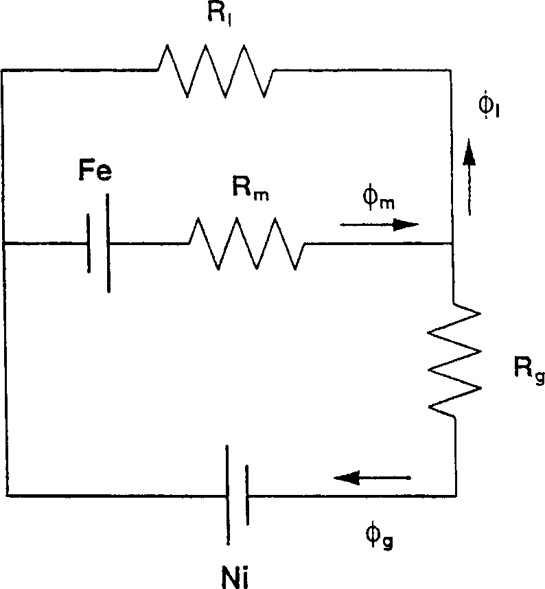
[0016] figure 1 An equivalent circuit is shown for the magnetic circuit structure of the rotating electrical machine of the embodiment of the present invention. exist figure 1 In the shown equivalent circuit, the following equations (1) to (4) are satisfied:

[0017] φ m = φ l +φ g (1)

[0018] φ r =B r ·a m (2)

[0019] f e -R m ·φ m =R m (φ r -φ m ) = R g ·φ g -N i (3)

[0020] R m (φ r -φ m ) = φ l · R l (4)

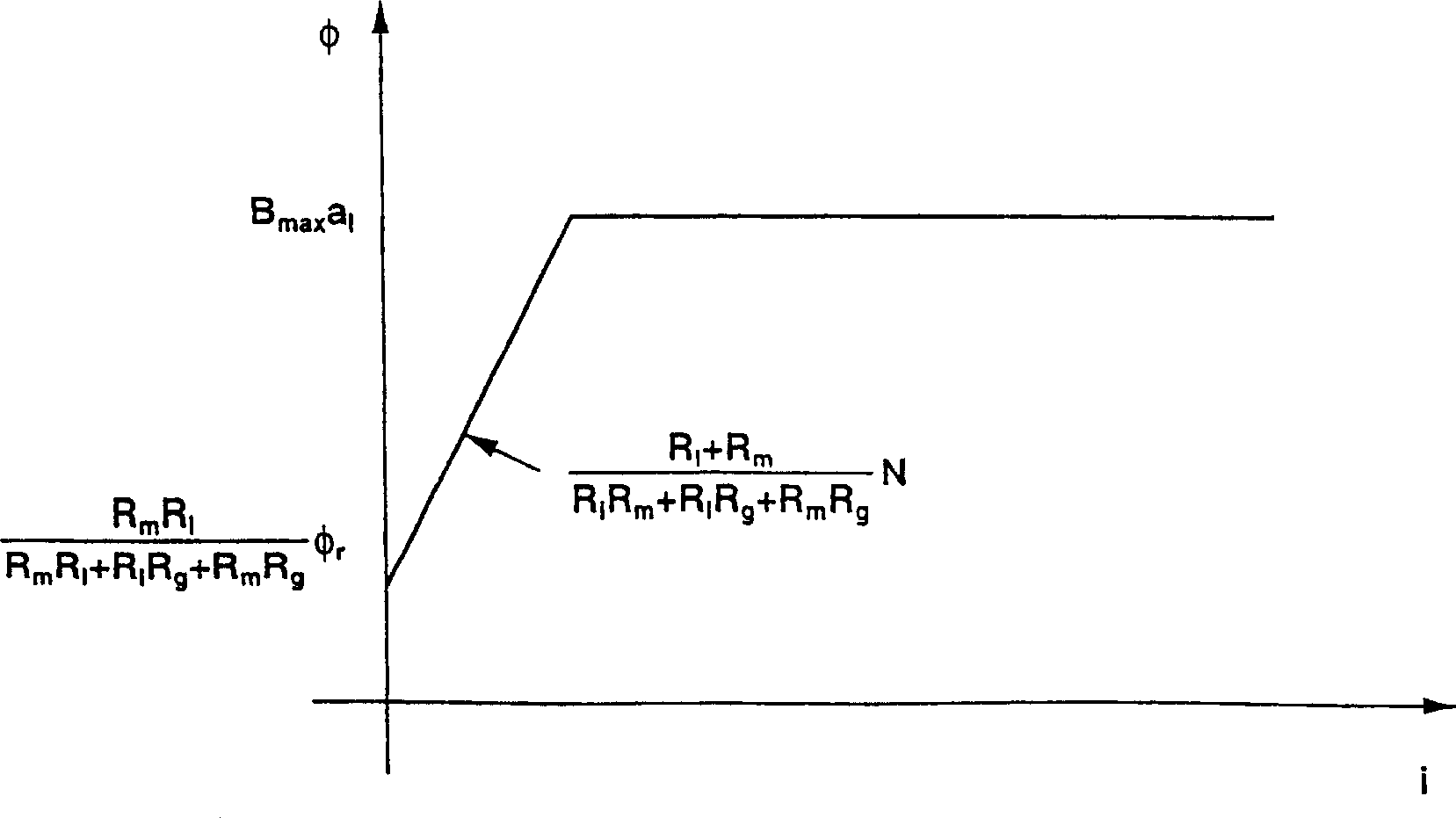
[0021] In these equations, φ m is the permanent magnet flux, φ l is the leakage flux, φ g is the air gap flux, R l is the reluctance of the leakage flux at the end of the permanent magnet, N i is the magnetomotive force of the armature coil, φ r is the magnetic flux in the permanent magnet without magnetic field, B r is the residual flux density of the permanent magnet, a m is the cross-sectional area of ​​the permanent magnet, F...


PUM


Abstract

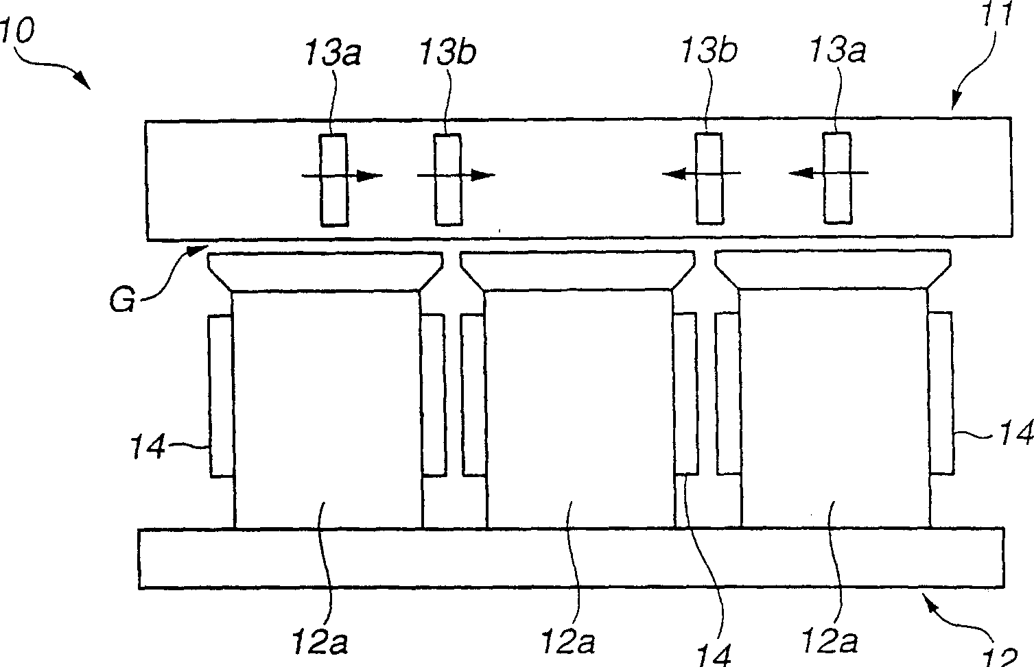
A rotary electric machine Includes a rotor including a plurality of magnet sections arranged along a rotational direction of the rotor so that polarities of the magnet sections change alternately, and a stator including armature coils, and being disposed to confront the rotor across an air gap. Permanent magnet flux which is not linked with one of the air gap and the armature coils is higher than permanent magnet flux which is linked with the air gap and the armature coils in a no-load state.

Description

technical field [0001] The present invention relates to a magnetic circuit structure for a rotating electrical machine, and more particularly to a magnetic circuit structure for a rotating electrical machine such as a permanent magnet motor. Background technique [0002] U.S. Patent No. 5,631,512 (corresponding to Japanese Patent Application Laid-Open No. H07(1995)-336919) shows a permanent magnet motor including a rotor and a plurality of permanent magnets connected with permanent magnets The fixed intervals with the same circumferential length are arranged along the circumferential direction. The permanent magnet motor also includes a salient pole made of soft magnetic material, located between two adjacent permanent magnets and arranged to have the same thickness as that of the permanent magnets. [0003] The permanent magnet motor described above has an IPM (Inner Permanent Magnet) structure of inverse salient polarity, and thus the magnetic flux is always coupled with ...

Claims


Application Information

Patent Timeline
Patent Type & Authority Applications(China)
IPC IPC(8): H02K1/27H02K1/12
CPCH02K29/03H02K1/2766H02K1/2793H02K1/2795
Inventor 有满稔赤津观
Owner NISSAN MOTOR CO LTD
Features
  • R&D
  • Intellectual Property
  • Life Sciences
  • Materials
  • Tech Scout
  • Unparalleled Data Quality
  • Higher Quality Content
  • 60% Fewer Hallucinations
Learn More