Touch panel

A touch panel and substrate technology, applied in the direction of instrument, electrical digital data processing, data processing input/output process, etc., can solve the problems of increasing the number of parts and manufacturing costs, and prevent the increase in the number of parts and manufacturing costs. The effect of reducing and reducing the number of parts

Inactive Publication Date: 2006-04-12
SANYO ELECTRIC CO LTD
View PDF1 Cites 21 Cited by
  • Summary
  • Abstract
  • Description
  • Claims
  • Application Information

AI Technical Summary

Problems solved by technology

[0002] In the past, light-emitting components and light-receiving components were installed in separate modules on the outer periphery of the display unit, which resulted in an increase in the number of parts and an increase in manufacturing costs.

Method used


Image

  • Touch panel
  • Touch panel
  • Touch panel

Examples


Embodiment Construction

[0043] the following by means of Figure 1 to Figure 19 , to describe the embodiments of the present invention in detail.

[0044] Figure 1 to Figure 5 It is the first example illustrating the present invention.

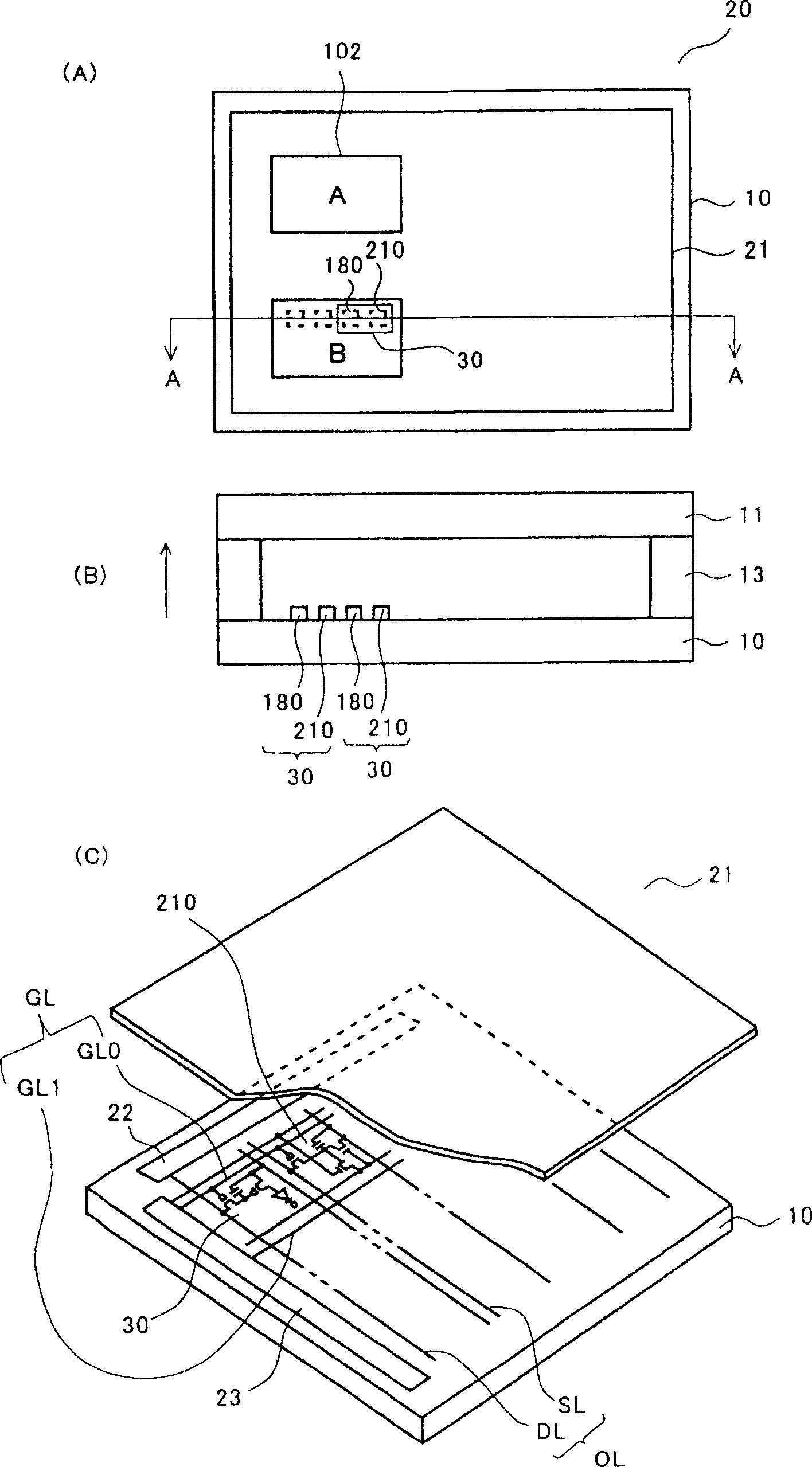
[0045] figure 1 is a schematic diagram illustrating the touch panel of this embodiment, figure 1 (A) is a floor plan, figure 1 (B) for figure 1 A schematic A-A sectional view of (A), figure 1 (C) is an exploded oblique view.

[0046] The touch panel 20 includes a display unit 21 in which display pixels 30 are arranged in a matrix on a substrate 10 .

[0047] like figure 1 As shown in (A), the substrate 10 is an insulating substrate such as glass. On the substrate 10 , for example, display pixels 30 are used to display buttons 102 for a user to perform specific operations. The opposite substrate 11 is a transparent substrate such as glass that allows light from the display pixels 30 to pass through. The opposite substrate 11 and the substrate 10 are a...


PUM


Abstract

The present invention relates to a touch panel, and a photosensor and the display part are fabricated on the same substrate. Input coordinates are specified by comparing the light quantities among positions (pixels) of contact or non-contact by a finger or the like by using a comparator. This allows TFTs constituting the photosensor to be fabricated on the same substrate in the same process as the pixels, and it is thereby possible to reduce the manufacturing cost and the number of components. A region for disposing a sensor in the outer portion becomes unnecessary, which allows downsizing of the device. Moreover, effective use of the display part is possible because blind spots are eliminated from the display part. It is possible to improve the precision of input recognition and to perform detection uniformly over the entire display part. Furthermore, since the photosensor comprises a photoreceptor circuit capable of adjusting the light-receiving sensitivity, it is possible to achieve uniform light-receiving (detection) sensitivity for the display part.

Description

technical field [0001] The present invention relates to a touch panel, and more particularly, to a touch panel in which an optical sensor is mounted on the same substrate as a display unit. Background technique [0002] In the past, the light emitting unit and the light receiving unit are arranged in separate modules on the outer periphery of the display portion, which leads to an increase in the number of parts and an increase in manufacturing cost. [0003] Due to market requirements for miniaturization, light weight, and thinning of the current display components, flat panel displays (FPDs) are being widely used. Most of such display units are equipped with, for example, an optical touch panel that detects input coordinates by blocking light, and an optical sensor that detects external light to control the screen brightness of the display. [0004] For example, Figure 20 It is an example of an optical touch panel. Figure 20 The optical touch panel 300 shown in (A) is p...

Claims


Application Information

Patent Timeline
Patent Type & Authority Applications(China)
IPC IPC(8): G06F3/033G06K11/06
CPCG06F3/0412G06F3/042G06F3/0421G06F3/04166
Inventor 小川隆司松本昭一郎
Owner SANYO ELECTRIC CO LTD
Why Eureka
Try Eureka