
Source driver, electro-optic device, and electronic instrument

A source driver, optoelectronic device technology, applied in the direction of televisions, instruments, electrical components, etc., can solve problems such as power consumption, achieve low power consumption, realize power consumption, and reduce power consumption.

Inactive Publication Date: 2006-04-12
SEIKO EPSON CORP
View PDF1 Cites 15 Cited by
  • Summary
  • Abstract
  • Description
  • Claims
  • Application Information

AI Technical Summary

Problems solved by technology

Therefore, in the energy-saving driving mode, for example, although only the highest-order data of the display data is required, the voltage level of the unnecessary low-order signal is also changed, and a penetrating current is generated due to the conversion of the voltage level. Useless power is consumed

Method used


Image

  • Source driver, electro-optic device, and electronic instrument
  • Source driver, electro-optic device, and electronic instrument
  • Source driver, electro-optic device, and electronic instrument

Examples


Embodiment Construction

[0039] Hereinafter, embodiments of the present invention will be described in detail with reference to the drawings and the like. In addition, the embodiments described below do not unduly limit the contents of the present invention described in the claims. Furthermore, not all of the configurations described below are necessarily essential components of the present invention.

[0040] 1. Photoelectric device

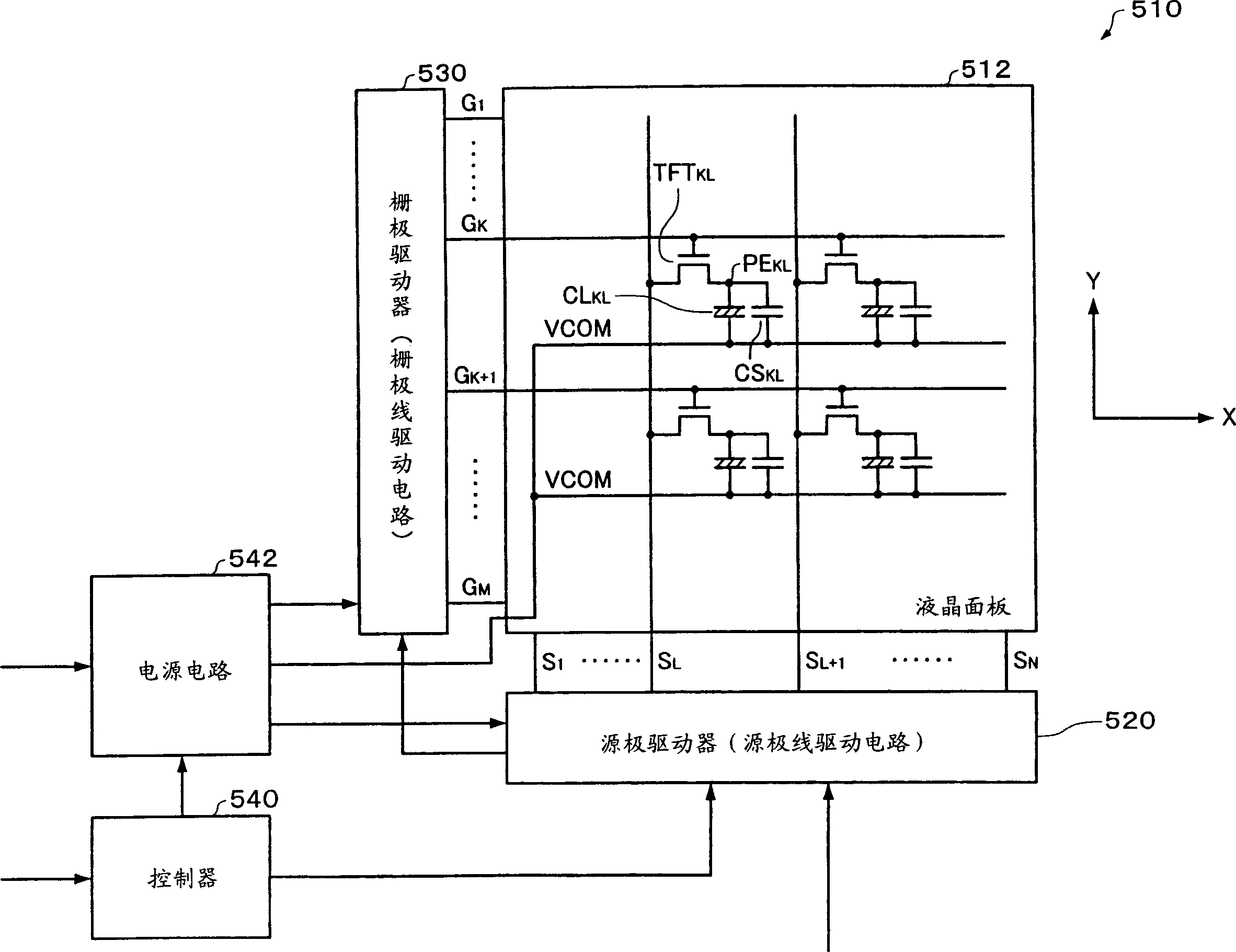
[0041] figure 1 An example of a block diagram of a display device including a photoelectric device to which the source driver of this embodiment is applied is shown. exist figure 1 Among them, a liquid crystal panel is used as an optoelectronic device. exist figure 1 Among them, a display device including the liquid crystal panel is called a liquid crystal device.

[0042] A liquid crystal device (in a broad sense, a display device) 510 includes a liquid crystal panel (in a broad sense, a photoelectric device) 512, a source driver (a source line drive circuit) 520...


PUM


Abstract

The pesent invention provides a source driver capable of reducing power consumption accompanying conversion operation of a level shifter in accordance with the driving mode, to provide an electro-optical device including the source driver and to provide electronic equipment. The source driver 520 comprises a drive mode setting register 690 for setting the source driver to normal drive mode or power saving drive mode, first to sixth level shifters LST1to LST6for converting the amplitude of each bit signal of 6 bits-display data, an operational amplifier OPAMP1for driving a source line based on a gradation voltage corresponding to an output signal of the first to sixth level shifters LST1to LST6in the normal drive mode and a voltage setting circuit VSET1for setting a voltage corresponding to uppermost bit data of the display data to an output of the operational amplifier OPAMP1in the power saving drive mode. In the power saving drive mode, only an input signal of the first to fifth level shifters LST1to LST5is fixed.

Description

technical field [0001] The invention relates to a source driver, an optoelectronic device and electronic equipment including the source driver. Background technique [0002] Conventionally, as liquid crystal panels (photoelectric devices) used in electronic equipment such as mobile phones, there are simple matrix liquid crystal panels and switching elements using thin film transistors (Thin Film Transistor: hereinafter abbreviated as TFT) and the like. Source matrix liquid crystal panel. [0003] The advantage of the simple matrix type liquid crystal panel is that it is easier to achieve lower power consumption than the active matrix type liquid crystal panel. On the contrary, its disadvantage is that it is difficult to display multiple colors or moving images. On the other hand, an active matrix type liquid crystal panel is advantageous in that it is suitable for multi-color display or moving image display, but has a disadvantage in that it is difficult to achieve low powe...

Claims


Application Information

Patent Timeline
Patent Type & Authority Applications(China)
IPC IPC(8): G09G3/36G09G3/20G02F1/133
CPCG09G2360/18G09G2310/027G09G2330/021G09G2340/0428G09G2310/0289G09G3/3688G09G3/3611G09G3/20H04N5/66
Inventor 仁科多美子牧克彦
Owner SEIKO EPSON CORP
Learn More