Voltage-controlled oscillator

A technology of voltage-controlled oscillators and piezoelectric vibrators, applied in power oscillators, electrical components, etc., can solve problems such as narrow frequency variable range, large capacitance value, and inability to switch voltage settings by capacitance

Inactive Publication Date: 2006-04-12
コラボイノベーションズインコーポレイテッド
View PDF2 Cites 5 Cited by
  • Summary
  • Abstract
  • Description
  • Claims
  • Application Information

AI Technical Summary

Problems solved by technology

[0008] As the first problem of the conventional voltage-controlled oscillator as described above, there is a problem that since the DC bias voltage at the drain terminal is determined on the amplifier side of the oscillator circuit, the capacitive switching voltage cannot be set to a desired value, thus making Impossible to control the frequency about the desired gate voltage
[0010] Also, as a third problem, there is a problem that the frequency variable range is narrow because the capacitance value is large when it is equal to or less than the capacitance switching voltage
This is because the frequency vs. capacitance characteristic describes an exponential curve, so the frequency variable range with respect to the capacitance change is narrow in the case where the capacitance value is large when equal to or less than the capacitance switching voltage

Method used


Image

  • Voltage-controlled oscillator
  • Voltage-controlled oscillator
  • Voltage-controlled oscillator

Examples


Embodiment 1

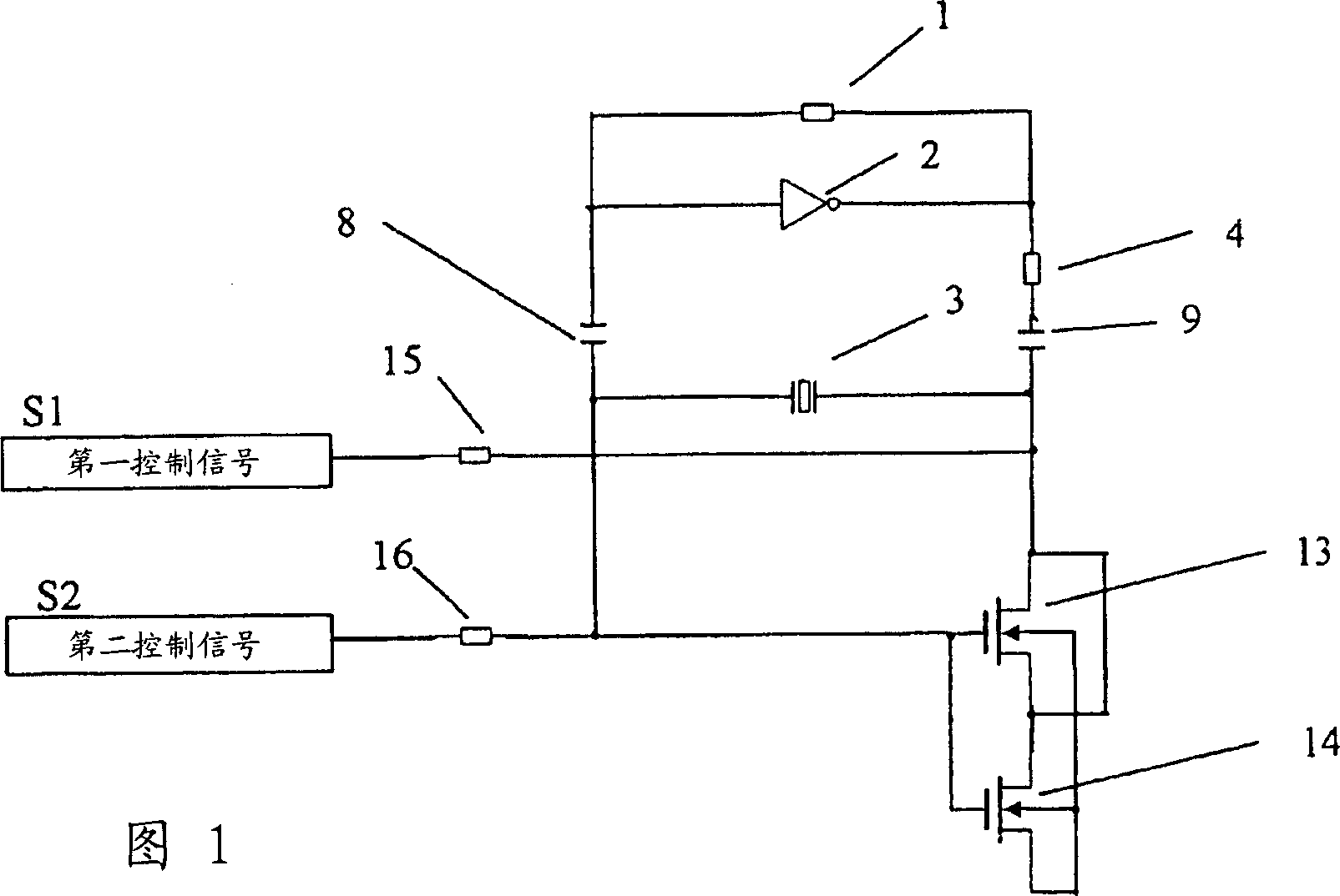
[0047] In the voltage controlled oscillator of Embodiment 1, for example, the first MOS transistor 13 as a variable capacitor is provided, and its source and drain terminals are short-circuited, and the second MOS transistor 14 is connected to the first MOS transistor 13 at its source terminal. The source and drain terminals are shorted. The first and second MOS transistors 13 , 14 have back-gate terminals which are short-circuited to the source terminal of the second MOS transistor 14 . Meanwhile, the first and second MOS transistors 13, 14 have gate terminals shorted together. Therefore, a variable capacitance device is constituted using capacitance between the source and drain terminals of the first MOS transistor 13, the drain terminal of the second MOS transistor 14, and the gate terminals of the first and second MOS transistors.

[0048] That is, the voltage controlled oscillator shows an oscillator circuit composed of an amplifier having a feedback resistor 1 and an in...

Embodiment 2

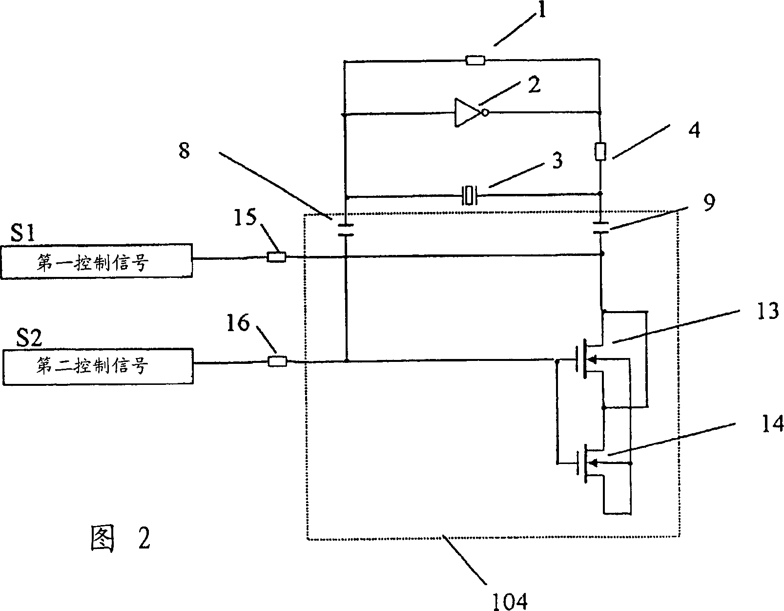
[0053] FIG. 2 is a circuit diagram showing a schematic configuration of a voltage-controlled oscillator in Embodiment 2 of the present invention.

[0054] Embodiment 2 shows an oscillating circuit composed of a feedback resistor 1, an amplifier 2, and a quartz oscillator 3 forming a feedback circuit. A series connection 104 with a direct connection of the first DC blocking capacitor 8 , the variable capacitor formed by the MOS transistors 13 , 14 of the above-described embodiment and the second DC blocking capacitor 9 is used as the load capacitor.

[0055] At the same time, the first and second MOS transistors 13, 14 as capacitors have a gate terminal and a source-drain terminal, and the MOS transistor threshold value is input to the gate terminal and the source-drain terminal through the high-frequency removal resistors 15, 16 Any one of control signal or temperature compensation control signal and external voltage frequency control signal.

[0056] The others are similar t...

Embodiment 3

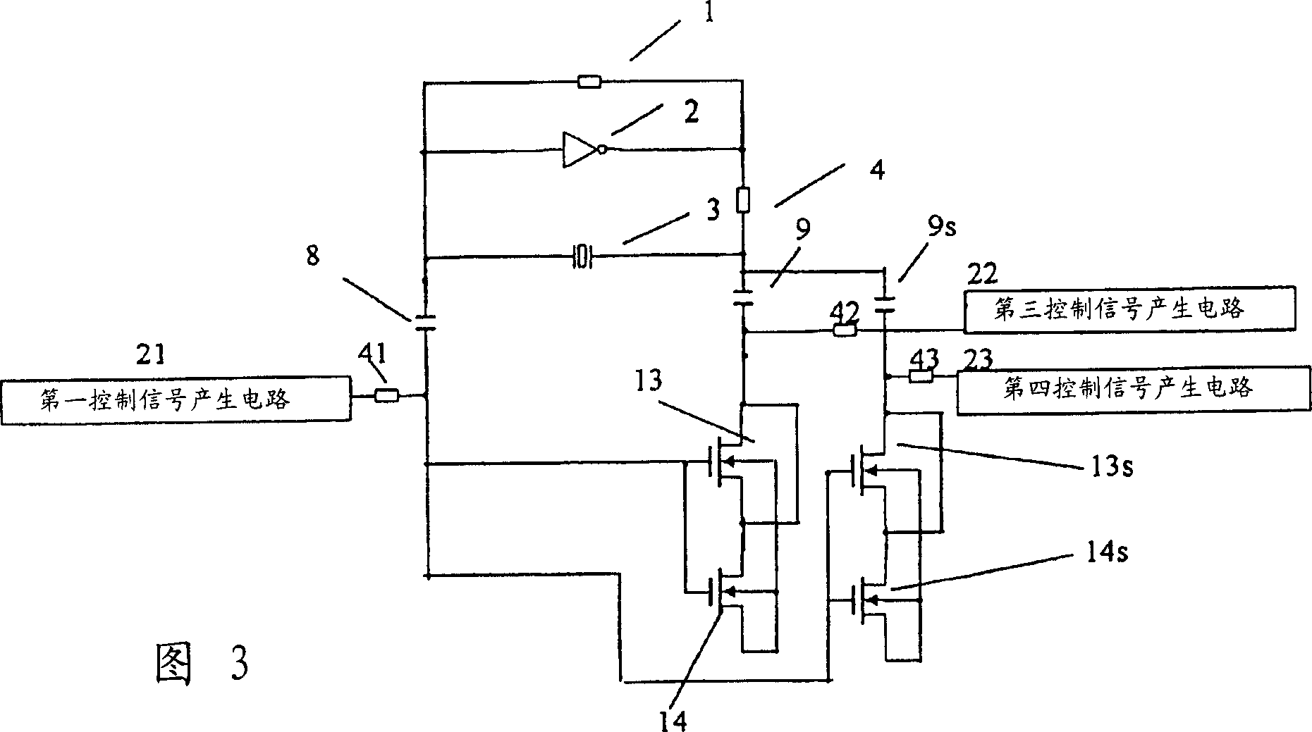
[0061] Embodiment 3 is characterized in that the MOS transistor is divided into a plurality, as shown in FIG. 3, so as to form two sets of variable capacitors, and this configuration enables While the control is similarly performed, the capacitive switching voltage is independently controlled by the temperature compensation control signal and the external voltage frequency control signal.

[0062] In this embodiment, in addition to Embodiment 2, a variable capacitance element formed of the first MOS transistor 13 and the second MOS transistor 14 is provided as the first variable capacitance. At the same time, the third MOS transistor 13S is short-circuited at its source terminal S3 and drain terminal D3 to further short-circuit it with the drain terminal D4 of the fourth MOS transistor 14S. The back gate terminals BG3, BG4 of the third and fourth MOS transistors 13S, 14S are short-circuited with the source terminal S4 of the fourth MOS transistor 14S. At the same time, the ga...


PUM


Abstract

An oscillator circuit configured by a feedback resistance 1 , an amplifier 2 and a quartz vibrator 3 has a load resistance. MOS transistors 5, 6 short-circuited at source and drain terminals has a capacitance, as a variable capacitance, occurring at between the source-drain terminal and gate terminal. A series connection of DC-cut capacitance 8, 9 and variable capacitance (MOS transistor 5, 6 ) is configured between one and the other terminals of the quartz vibrator 3 and an AC ground terminal. For example, a threshold voltage control signal for MOS transistor 5, 6 is inputted to the source-drain terminal through a high-frequency removing circuit 10, 11 . Meanwhile, a signal that a temperature compensation control signal and an external voltage frequency control signal are superimposed together is inputted to the gate terminal. This makes it possible to desirably determine an output bias to a temperature compensation control circuit and an external voltage frequency control circuit.

Description

technical field [0001] The present invention relates to voltage controlled oscillators, in particular to a voltage controlled oscillator used as a temperature compensated quartz oscillator under voltage control. Background technique [0002] Recently, due to the rapid advancement of mobile communication devices such as cellular phones, those communication devices require many increased functions including temperature compensation performance, size reduction, increased frequency of use, and the like. Therefore, in such a communication device, temperature compensation performance, size reduction, increase in frequency of use, and the like are required for a quartz oscillator used as a reference of a communication frequency. [0003] A temperature compensated quartz oscillator is a quartz oscillator that has a temperature compensation function and reduces frequency variations due to temperature variations, and is widely used as a reference frequency source for cellular phones a...

Claims


Application Information

Patent Timeline
Patent Type & Authority Applications(China)
IPC IPC(8): H03B5/32
CPCH03B5/366H03B5/04
Inventor 立山雄一
Owner コラボイノベーションズインコーポレイテッド
Why Eureka
Try Eureka