Dephasing control

a technology of dephasing control and control frequency, which is applied in the direction of synchronous motors, ac motor stoppers, dc source parallel operation, etc., can solve the problems of increasing the cost and complexity of the motor construction, increasing maintenance costs, and difficulty in controlling the velocity, so as to achieve greater processing capacity, reduce the effect of maintenance costs and low cos

Inactive Publication Date: 2012-04-12
MABE SA DE CV
View PDF9 Cites 15 Cited by
  • Summary
  • Abstract
  • Description
  • Claims
  • Application Information

AI Technical Summary

Benefits of technology

[0017]Thus the applications of this technology for household appliances can be in a wide array, this aided by the low cost of the micro-controllers, which have a greater processing capacity as time goes by, typically “pre-installed” or “built in” features which allow for the generating of PWM pulse trains and varying their frequencies with great ease.

Problems solved by technology

Thus this type of motors is desirable for other applications, such as household washers or refrigerators, where in the example with the washer it has the inconvenience of the velocity control, since these motors work very well at a constant velocity, it being rather difficult to control the velocity of these.
This type of motor construction turns at a certain undesired point upon knowing that the sliding rings require brushes or carbons, themselves elements of wearing which also allow the flow of current; this in addition to increasing the cost and complexity of the motor construction, thereby increasing maintenance cost.
Initially this solution has an interesting result but overlooks the motor slipping control, because it itself, upon feeling a frequency variation will tend to increase or decrease its velocity in relation to the frequency fed, but if the motor has coupled to its axis a large mechanical load which causes a great inertia, the rotor will not be able to follow the magnetic field frequency induced by the stator, thus increasing its dephasing or slip between the angular velocity or magnetic field frequency and the mechanical velocity of the rotor shaft.

Method used


Image

  • Dephasing control
  • Dephasing control
  • Dephasing control

Examples


Embodiment Construction

Definitions

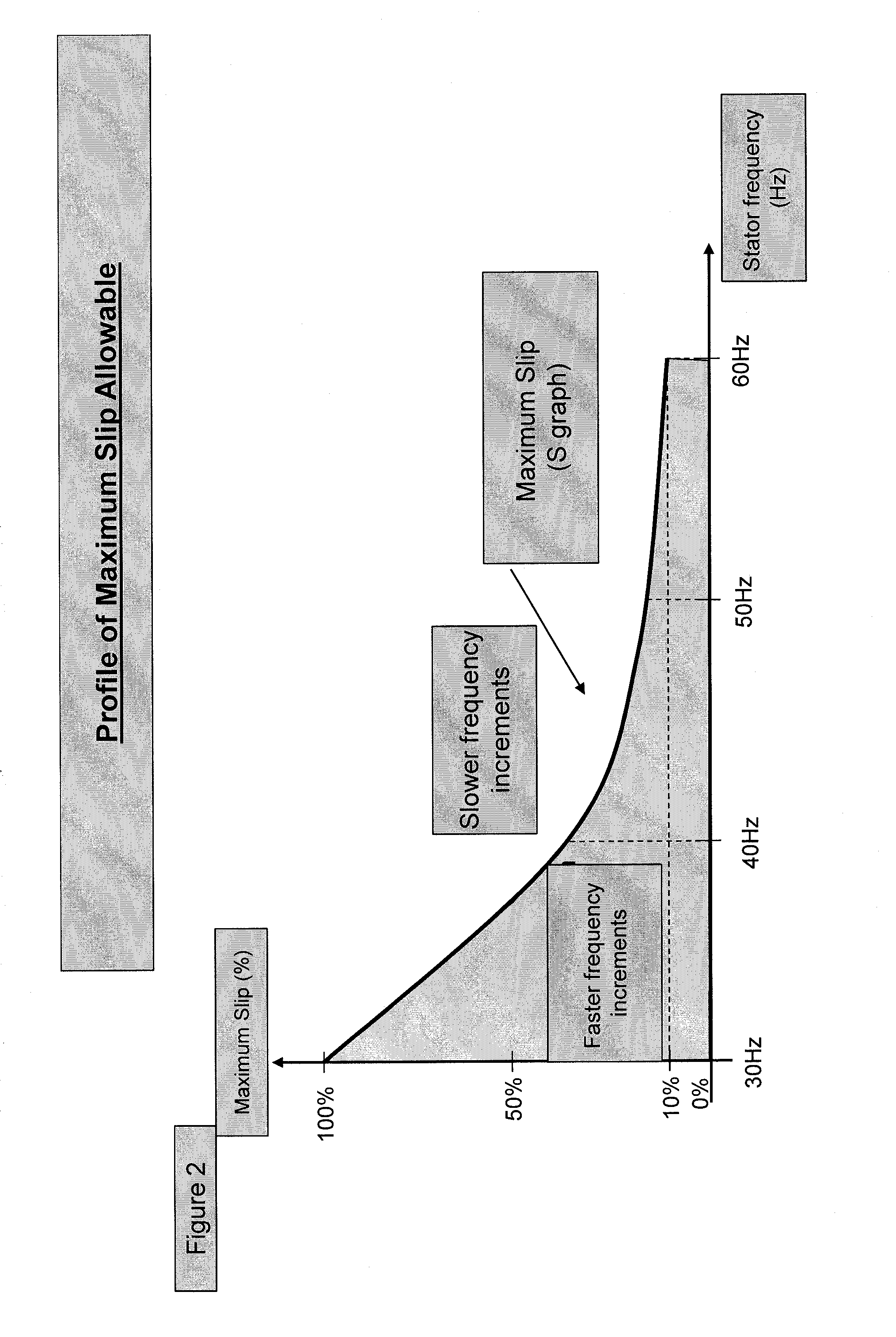
[0035]Slip—The magnetic field generated by the stator windings induce a voltage to the rotor, which generates a current flow on the cage bars. This current creates a magnetic field which reacts with the stator magnetic field, producing the torque which moves the motor. The rotor attempts to follow through its movements the stator magnetic field, turning to an angular velocity {acute over (ω)}. The rotor's turn velocity is only equal to that of the stator's {acute over (ω)}s when the motor is empty, that is, without friction. As the demand for torque increases on the axis, the motor decreases its velocity then turning at an angular velocity which is always lower than the stator angular velocity.

[0036]This is called slip and it is defined as:

s=ωs-ωωs

[0037]Where:

[0038]Ws is the angular velocity of the stator magnetic field;[0039]W is the rotor angular velocity; and[0040]S is the slip.

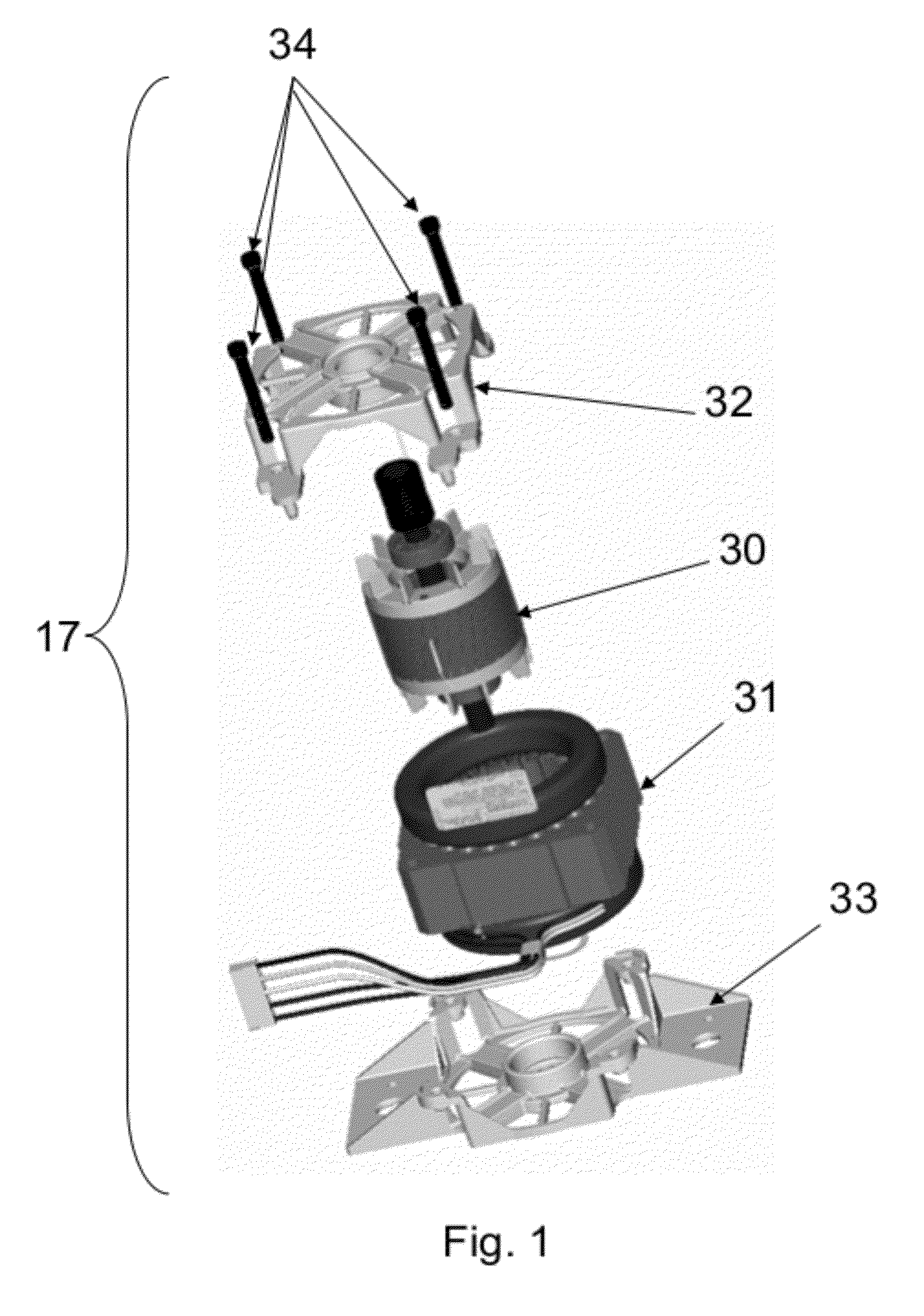
[0041]Induction Motor—Also known as “squirrel cage motor” owes its name to the rotor shape: ...


PUM


Abstract

A system to control an asynchronous tri-phase motor where said system comprises: at least one filter directly coupled to the current of the Alternative Current (AC) line; a rectifier which rectifies the line current, a doubler which reduces the curl, elevates the voltage and delivers a voltage in Direct Current, a braking resistance which helps to dissipate energy when the system is in braking mode, a shunt resistance, which helps to measure the current which flows from the V-line between the doubler and the IGBT module, a source, which adapts the voltage which the microcontroller consumes and peripheries (operational amplifiers, detectors, etc.), a line regulator to remove curls and line noise, a microcontroller to process, admit and emit control signals, a potential module which emits a PWM train pulse with a frequency determined by the microcontroller towards the IGBT module when the microcontroller indicates such, an IGBT module, which receives the PWM pulse train adapting and coupling them to an H bridge, to thus allow the flow of high voltage in DC emanating from the doubler towards the electric motor, a retro-feeding line towards the microcontroller to measure current, a velocity detector coupled mechanically to the motor and which sends a signal or pulse train towards the microcontroller; as well as the acceleration or braking methods consistent in the measurement of the slip S of said tri-phase motor.

Description

RELATED APPLICATIONS[0001]This application claims priority from Mexican Application Serial No. MX / a / 2010 / 011171 filed Oct. 11, 2010, which is incorporated herein by reference in its entirety.FIELD OF INVENTION[0002]The present invention lies in the field of electric motor control (induction) which can be used for diverse applications, both in industry in general as in household appliances in particular; showing in an illustrative manner but not limited to its application in washers.BACKGROUND OF THE INVENTION[0003]According to Irvin Gottlieb in his work titled “Electric Motors and Control Techniques”, Second Edition Page 72 McGraw Hill 1994 U.S.A., the induction motor can be understood as a rotary transformer, this due to the effect present in large capacity or very large transformers where the design of these present special attention to the mechanic repulsion force which exists between the primary and secondary coils; thus this repulsion phenomenon between coils in some way gives ...

Claims


Application Information

Patent Timeline
Patent Type & Authority Applications(United States)
IPC IPC(8): H02P3/22H02P23/08
CPCH02P23/08
Inventor HERNANDEZ FERRUSCA, OMAR ANTONIODIAZ FERNANDEZ, ALFREDO
Owner MABE SA DE CV
Why Eureka
Try Eureka