
Washing machine

A technology for washing machines and casings, applied in the field of washing machines, can solve the problems of increased flow resistance of flow channels, spraying of washing water W, long distance, etc., and achieve the effect of minimizing resistance

Inactive Publication Date: 2006-04-19
LG ELECTRONICS INC
View PDF0 Cites 35 Cited by
  • Summary
  • Abstract
  • Description
  • Claims
  • Application Information

AI Technical Summary

Problems solved by technology

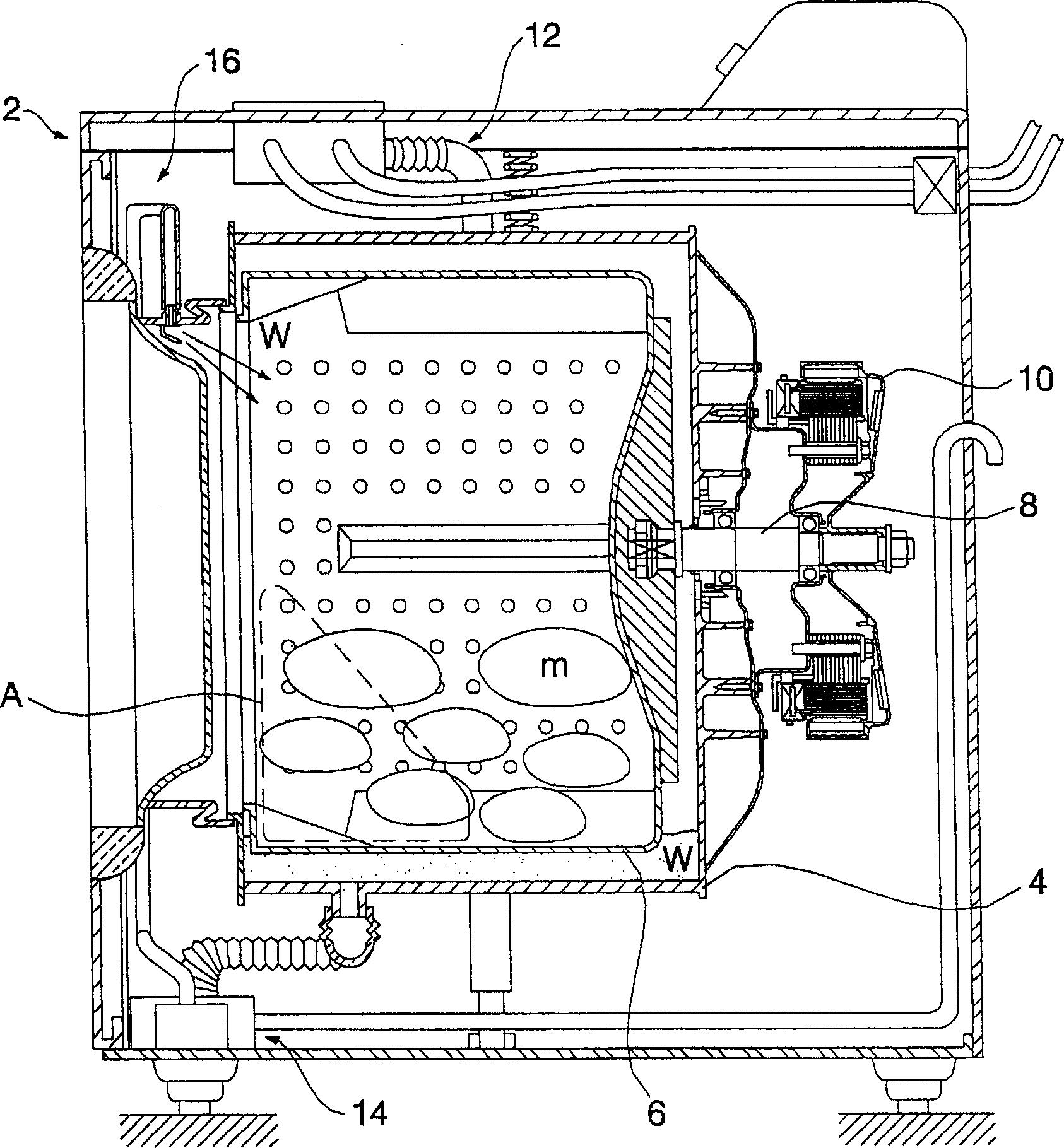
[0009] However, since the flow passage of the conventional washing machine that sucks the wash water W to the upper front side of the drum 6 has a long distance, the flow resistance in the flow passage increases, so it is difficult to quickly spray a large amount of wash water W into the drum 6. In drum 6
[0010] In addition, since the wash water W is sprayed into the drum 6 from the upper front side of the drum 6, a non-spray area A will be generated inside the drum, which causes the wash water W to be sprayed unevenly onto the laundry.

Method used


Image

  • Washing machine
  • Washing machine
  • Washing machine

Examples


Embodiment Construction

[0049] Preferred embodiments of the present invention will be described in detail with reference to the accompanying drawings. In the embodiments, similar components are denoted by the same reference numerals, so repeated description thereof will be omitted below.

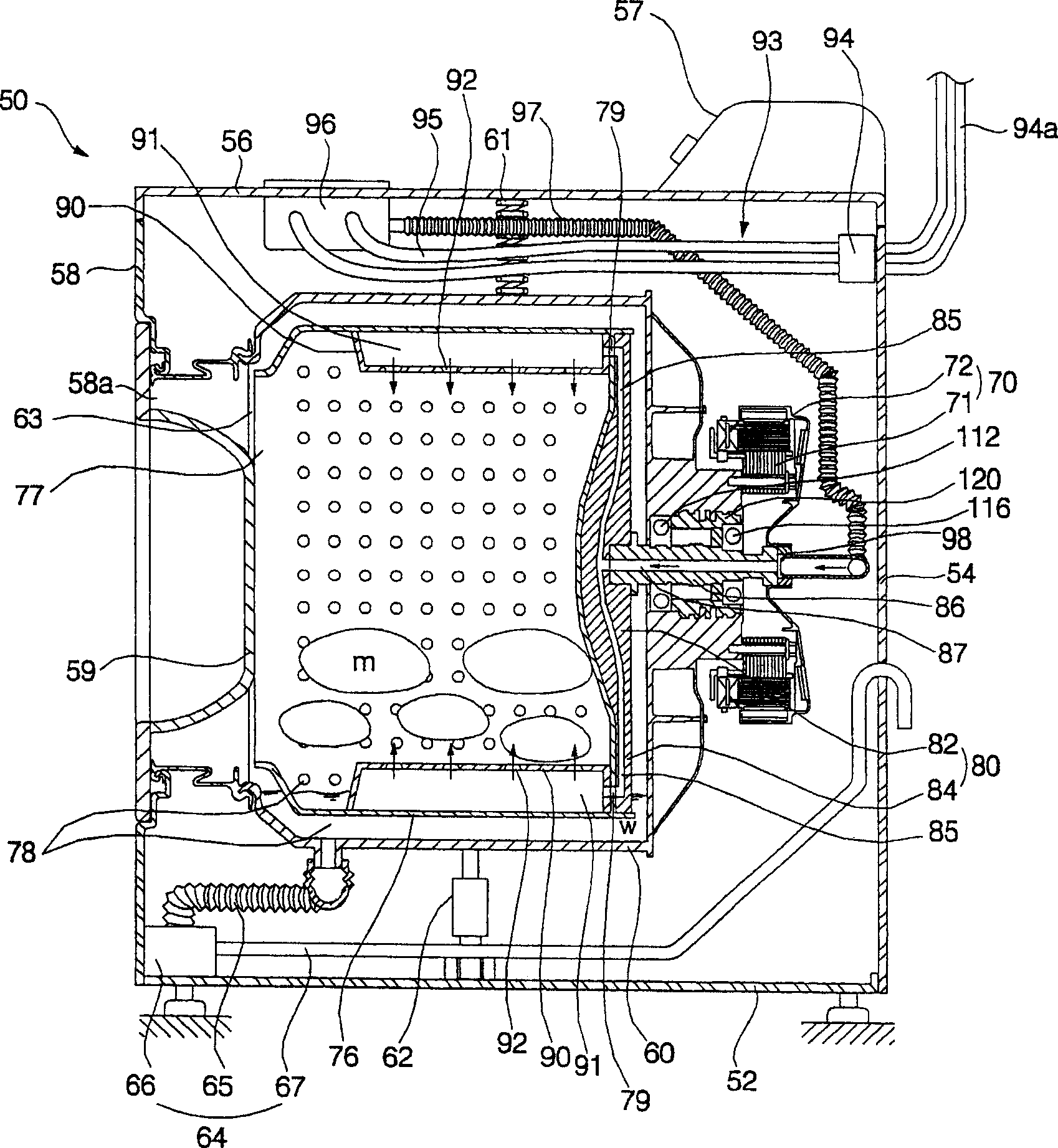
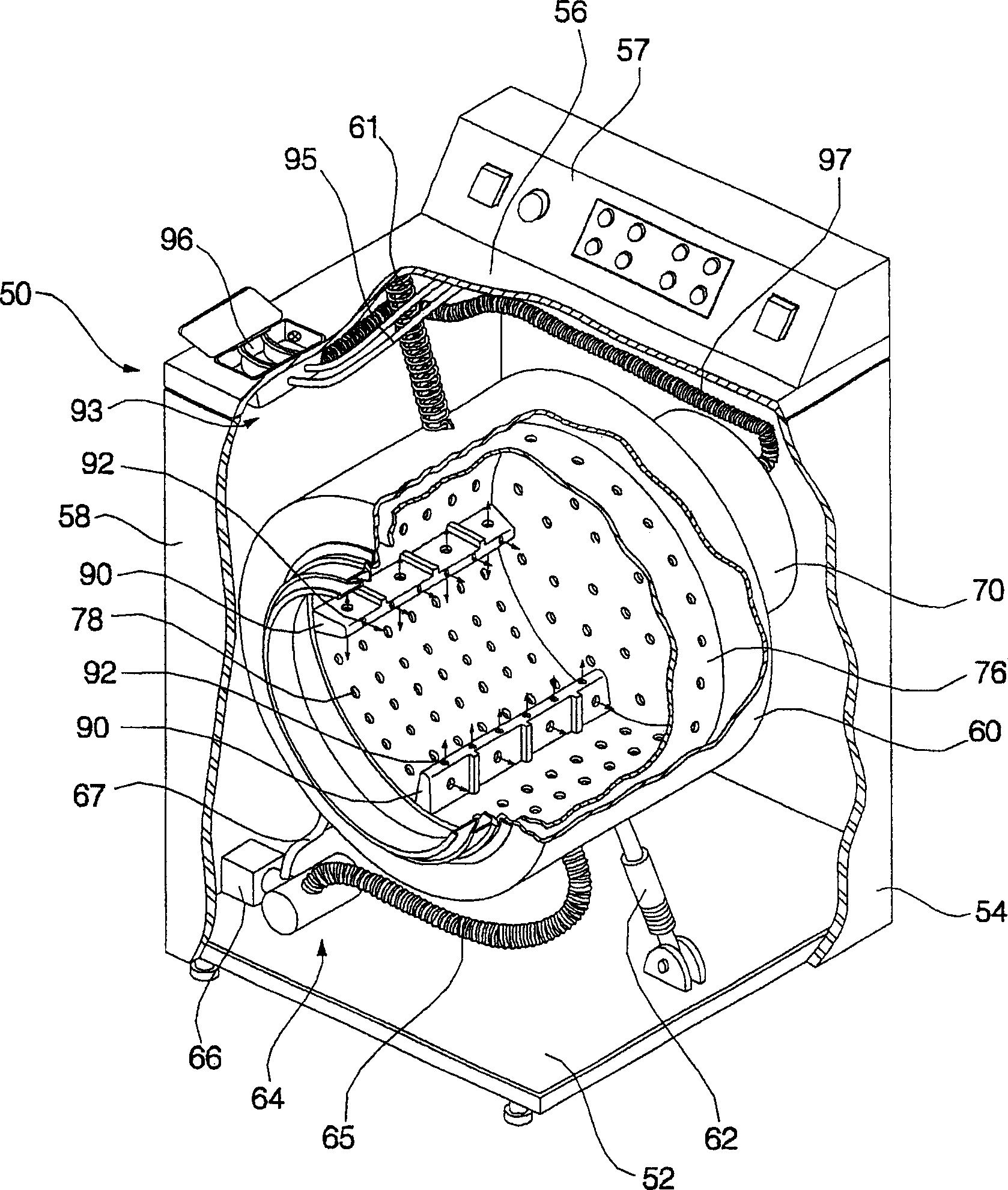
[0050] figure 2 A sectional view showing an internal structure of a washing machine according to a first embodiment of the present invention, image 3 A partially cutaway perspective view of a washing machine according to a first embodiment of the present invention is shown.

[0051] Such as figure 2 and image 3 As shown, the washing machine according to the first embodiment of the present invention includes: a cabinet 50, which defines the shape of the washing machine; a tub 60, which is supported in the cabinet 50; a drum 76, which is rotatably placed in the tub 60, For accommodating laundry m; a star structure 80, which is mounted on the drum 76; a drive shaft 86, which is connected to the star structure 8...


PUM


Abstract

A washing machine designed to uniformly and rapidly supply wash water into a drum through a drive shaft. The washing machine comprises a cabinet, a tub supported in the cabinet, a drum rotatably disposed within the tub for containing laundry, a spider mounted to the drum, a drive shaft connected to the spider to rotate the drum, at least one lifter mounted on an inner surface of the drum, and a water supply path formed to allow wash water to be supplied into the drum after passing through the drive shaft, the spider, the drum and the lifter. After sequentially passing through the drive shaft, the spider, the drum and the lifter, the wash water is then injected into the drum from the lifter, so that the wash water is rapidly and uniformly supplied to laundry, thereby enhancing washing and rinsing performance.

Description

technical field [0001] The present invention relates to a washing machine, and more particularly to a washing machine designed to supply washing water into a drum via a drive shaft. Background technique [0002] Generally, a washing machine is used to remove pollutants adhering to laundry, such as clothes, bedding, etc., accommodated in a drum through the interaction between water and detergent. Washing machines can be classified into agitator type washing machines, pulsator type washing machines, and drum type washing machines. [0003] The agitator type washing machine is adapted to wash laundry by rotating a washing rod protruding from the center of a drum left and right. The pulsator type washing machine is adapted to wash laundry using a frictional force between the laundry and a water flow formed by rotating a disk-shaped pulsator disposed at a lower portion of the tub left and right. A drum type washing machine is adapted to wash laundry by rotating a drum having a ...

Claims


Application Information

Patent Timeline
Patent Type & Authority Applications(China)
IPC IPC(8): D06F21/02D06F37/06D06F39/08
CPCD06F37/269D06F39/024D06F39/081D06F39/083D06F39/088
Inventor 金东源
Owner LG ELECTRONICS INC
Learn More