[0064]
[0065] [The overall structure of the air conditioner]
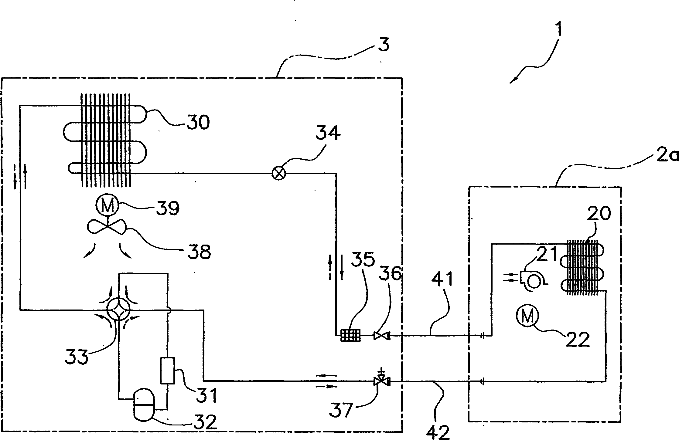
[0066] figure 1 The configuration of the air conditioner 1 and the basic configuration of the refrigerant circuit according to the first embodiment are shown.
[0067] The air conditioner 1 includes an indoor unit 2a mounted on an indoor wall surface or the like, and an outdoor unit 3 mounted outdoors.
[0068] The refrigerant circuit of the air conditioner 1 is mainly composed of the following components: an indoor heat exchanger 20 , an accumulator 31 , a compressor 32 , a four-way switching valve 33 , an outdoor heat exchanger 30 , and an electric expansion valve 34 .
[0069] The indoor heat exchanger 20 provided in the indoor unit 2a exchanges heat with the air in contact with it. In addition, the indoor unit 2a is provided with an indoor fan 21 for sucking indoor air and discharging the air after heat exchange by the indoor heat exchanger 20 into the room. An indoor fan motor 22 provided in the indoor unit 2a drives the indoor fan 21 to rotate. The detailed structure of the indoor unit 2a will be described later.
[0070] The outdoor unit 3 is provided with: a compressor 32; a four-way reversing valve 33 connected to the discharge side of the compressor 32; an accumulator 31 connected to the suction side of the compressor 32; The outdoor heat exchanger 30 on 33; the electric expansion valve 34 connected to the outdoor heat exchanger 30. The electric expansion valve 34 is connected to the piping 41 via the filter 35 and the liquid throttle valve 36 , and is connected to one end of the indoor heat exchanger 20 via the piping 41 . In addition, the four-way selector valve 33 is connected to the piping 42 via the gas throttle valve 37 , and is connected to the other end of the indoor heat exchanger 20 via the piping 42 . In addition, the outdoor unit 3 is further provided with an outdoor fan 38 for discharging the air heat-exchanged in the outdoor heat exchanger 30 to the outside. The outdoor fan 38 is rotationally driven by an outdoor fan motor 39 .
[0071] [Structure of indoor unit]
[0072] figure 2 (a) shows a front view of the indoor unit 2a, figure 2 (b) shows a side sectional view of the indoor unit 2a. figure 2 (a) and figure 2 (b) shows the indoor unit 2a when the operation is stopped.
[0073] The indoor unit 2a is a wall-mounted indoor unit installed on an indoor side wall, and the indoor unit has a casing main body 23 (casing) and a front panel 24a.
[0074] [shell body]
[0075] The case main body 23 has a horizontally long rectangular shape when viewed from the front, and has a vertically long rectangular cross-sectional shape when viewed from the side. Inside the casing main body 23, the above-mentioned indoor heat exchanger 20, indoor fan 21, indoor fan motor 22 (not shown) and the like are provided. like figure 2 As shown in (b), the indoor fan 21 is arranged in the center of the casing main body 23 when viewed from the side, and the indoor heat exchanger 20 having an inverted V shape is arranged so as to surround the upper half of the indoor fan 21 . In addition, the casing main body 23 is provided with a suction port 25 and an air outlet 26 .
[0076] The suction port 25 is an opening for passing the air sucked into the casing body 23 from the room by the indoor fan 21 , and has a first suction port 27 (suction port) and a second suction port 28 . The first suction port 27 has a shape long in the horizontal direction when viewed from the front, and its length is slightly smaller than the width W of the casing body 23 . like figure 2 As shown in (b), the first suction port 27 is provided in the vicinity of the front center of the casing main body 23 and faces the front side of the indoor heat exchanger 20 . The second suction port 28 is formed of a plurality of slits that are long in the longitudinal direction of the casing body 23 , and the second suction port 28 is provided on the top surface of the casing body 23 .
[0077] The air outlet 26 is an opening for passing the air that has passed through the indoor heat exchanger 20 and is blown into the room by the indoor fan 21 . like image 3 As shown in (a), the air outlet 26 has a shape long in the horizontal direction, and its length is slightly smaller than the width W of the casing body 23 . In addition, the air outlet 26 is located in the vicinity of the lower part of the casing body 23 , and the air outlet 26 is provided on the front surface of the casing body 23 . in addition, image 3 (a) is a front view during operation of the indoor unit 2a.
[0078] In addition, a horizontal damper 29 is provided in the vicinity of the air outlet 26 . The horizontal damper 29 is a plate-like member having an elongated shape in the longitudinal direction of the indoor unit 2a, and guides the air blown out from the air outlet 26. As shown in FIG. The horizontal damper 29 has a rotation shaft parallel to the longitudinal direction of the indoor unit 2a, and the air guide direction is changed by rotating the horizontal damper 29 around the rotation shaft.
[0079] [Front panel]
[0080] When viewed from the front, the front panel 24a covers the air outlet 26 and the first suction port 27 and opens and closes the air outlet 26 and the first suction port 27 . The front panel 24 a is a panel assembly in which a plurality of seamless panels are assembled, and includes a first panel 241 and a second panel 242 .
[0081] The first panel 241 is arranged below the front surface of the case body 23 . The first panel 241 is supported and movable by a movement mechanism (not shown), and the first panel 241 opens and closes the air outlet 26 . The first panel 241 is a seamless rectangular plate-shaped member, its width is substantially the same as the width W of the case body 23 when viewed from the front, and its height is substantially half the height H of the case body 23 . like figure 2 As shown in (b), the first panel 241 is in a state parallel to the vertical direction in a state in which the air outlet 26 is closed. In addition, in this state, when viewed from the front, the first panel 241 has a larger projected area than the air outlet 26 . Therefore, the first panel 241 completely covers the lower half of the front surface of the casing body 23 including the air outlet 26 in a state where the air outlet 26 is closed.
[0082] The second panel 242 is arranged above the front surface of the case body 23 . The second panel 242 is supported and movable by a moving mechanism (not shown), and the second panel 242 opens and closes the first suction port 27 . Like the first panel 241, the second panel 242 is a seamless rectangular flat plate-like member, and has a width substantially the same as the width W of the case body 23 including the first suction port 27 when viewed from the front, and the about half the height H of the body main body 23 . like figure 2As shown in (b), the second panel 242 is in a state parallel to the vertical direction in a state in which the first suction port 27 is closed. In this state, the second panel 242 is positioned above the first panel 241 and is aligned with the first panel 241, and the second panel 242 has a larger projected area than the first suction port 27 when viewed from the front. Therefore, the second panel 242 completely covers the upper half of the front surface of the case body 23 including the first suction port 27 in a state where the first suction port 27 is closed.
[0083] In this way, the first panel 241 completely covers the lower half of the front surface of the casing body 23 including the air outlet 26 in a state where the air outlet 26 is closed. The second panel 242 completely covers the upper half of the front surface of the case body 23 including the first suction port 27 in a state where the first suction port 27 is closed. Moreover, the 1st panel 241 and the 2nd panel 242 are arrange|positioned side by side up and down without a gap. Therefore, as figure 2 As shown in (a), the front panel 24a composed of the first panel 241 and the second panel 242 is in a state where the air outlet 26 and the first suction port 27 are closed, and substantially completely covers the entire front of the indoor unit 2a. state. Therefore, in this state, when viewed from the front, only the front panel 24a enters the field of vision of the occupant and the like, and the air outlet 26 and the first suction port 27 do not enter the field of vision of the occupant or the like. In addition, the front panel 24a has no other seam on the surface except for the seam extending in the horizontal direction formed by the upper end of the first panel 241 and the lower end of the second panel 242 . In addition, the first panel 241 is parallel to the vertical direction, and the second panel 242 is also parallel to the vertical direction. Therefore, the front panel 24a forms a flat surface 243 parallel to the vertical direction in a state in which the air outlet 26 and the first suction port 27 are closed.
[0084] [Operation of indoor unit]
[0085] Next, the operation when the indoor unit 2a of the air conditioner 1 performs the air-conditioning operation will be described.
[0086] When the indoor unit 2a is stopped, as described above, the front panel 24a is in a state in which the air outlet 26 and the first suction port 27 are closed.
[0087] When the indoor unit 2a is operating, first, the indoor fan 21 is started at a low rotational speed.
[0088] Next, the front panel 24a is moved, and the air outlet 26 and the first suction port 27 are opened. In this way, the air volume of the air sucked into the indoor unit 2a can be secured, and the air can be blown out in the horizontal direction. In this case, as image 3 As shown in (b), the second panel 242 moves in parallel forward. Thereby, the 1st suction port 27 is opened. In addition, in conjunction with the movement of the second panel 242, the first panel 241 moves vertically upward. Then, a part of the upper side of the first panel 241 is inserted between the second panel 242 and the case body 23 . Thereby, the blower outlet 26 is opened.
[0089] After the front panel 24a is moved to open the air outlet 26 and the first suction port 27, the horizontal damper 29 is rotated and moved so as to form an air outlet angle corresponding to the set operation mode.
[0090] As described above, the operation of the indoor unit 2a is performed.
[0091] When the indoor unit 2a is stopped, the front panel 24a moves, such as figure 2 (a) and figure 2 As shown in (b), it returns to the state in which the blower outlet 26 and the 1st suction port 27 were closed.
[0092] [feature]
[0093] <1>
[0094] In the indoor unit 2a of the air conditioner 1, when the operation is stopped, the front panel 24a covers the entire front surface of the indoor unit 2a. Also, the front panel 24a forms a flat surface 243 parallel to the vertical direction. Therefore, when the indoor unit 2a is stopped, when viewed from the front, only the flat front panel 24a is exposed to the visual field of the occupant or the like. In addition, on the surface of the front panel 24a, only the seam extending in the lateral direction (horizontal direction) serving as the boundary between the first panel 241 and the second panel 242 is exposed, and other seams are not exposed. Therefore, when viewed from the front, no longitudinally (vertically) extending seams are exposed on the indoor unit 2a, and only a minimum amount of laterally extending seams are exposed. Therefore, in the indoor unit 2a of the air conditioner 1, when viewed from the front, the appearance when the operation of the indoor unit 2a is stopped is matched with the indoor wall surface, and the appearance is improved.
[0095] <2>
[0096] Generally, since the wall-mounted indoor unit is arranged on the wall surface of the room, the front part tends to enter the field of vision of the occupant or the like. In addition, in many cases, the area of the front part of the indoor unit is large. Therefore, the present invention which improves the appearance when viewed from the front is particularly effective when the operation is stopped.
[0097] <3>
[0098] In the indoor unit 2a of such an air conditioner 1, when the first panel 241 and the second panel 242 are moved, the air outlet 26 and the first suction port 27 are opened. Therefore, the air intake into the indoor unit 2a and the air blowout from the indoor unit 2a can be sufficiently performed.
[0099] In addition, when the air outlet 26 and the first suction port 27 are opened, the first panel 241 may be moved up and down, and the second panel 242 may be moved slightly forward. Therefore, the thickness D of the indoor unit 2a during operation (refer to image 3 (b)) The increase is small. Therefore, in the indoor unit 2a of the air conditioner 1, the indoor unit 2a during operation can be configured compactly.
[0100] <4>
[0101] In the indoor unit 2a of such an air conditioner 1, the indoor fan 21 is activated at a low rotational speed before the front panel 24a is opened. In this case, since the indoor fan 21 rotates with the front panel 24a closed, the air inside the indoor unit 2a can be stirred. Therefore, during the cooling operation, the odor remaining inside the indoor unit 2a is absorbed by the moisture condensed on the indoor heat exchanger 20 . Therefore, the odor leaking into the room can be reduced. In addition, during heating, the front panel 24a is kept in a closed state until the temperature of the indoor heat exchanger 20 rises, so that the feeling of draft at the initial stage of operation can be reduced.