Method for atom force microscope inducing single molecule DNA positoning mutation

An atomic force microscope and single-molecule technology, applied in the biological field, can solve problems such as the inability to induce mutagenesis of a single DNA molecule, and achieve the effects of position determination, controllable operation, and easy implementation

Inactive Publication Date: 2006-05-03
SHANGHAI JIAO TONG UNIV
View PDF0 Cites 6 Cited by
  • Summary
  • Abstract
  • Description
  • Claims
  • Application Information

AI Technical Summary

Benefits of technology

The inventors developed an improved technique for modifying specific parts or regions within certain areas of DNA (called genes) that control important physiological processes such as growth, differentiation, developmental timing, etc., through manipulation applied mechanically over small sections called microsites. By doing this they could potentially create new ways to study these changes throughout their entire body.

Problems solved by technology

Technologies for studying how cells behave under different conditions have been developed during their study process called atomic force microscopic technique. However, current methods require manual laborious steps like adjustment of pressure applied to the material being studied, leading to errors caused by operator error. There is thus room for improvement through automating these processes without requiring human input.

Method used


Image

  • Method for atom force microscope inducing single molecule DNA positoning mutation
  • Method for atom force microscope inducing single molecule DNA positoning mutation
  • Method for atom force microscope inducing single molecule DNA positoning mutation

Examples


Embodiment

[0042] AFM localization of a sequence on the embodiment pBR322 plasmid DNA mechanically induced mutation

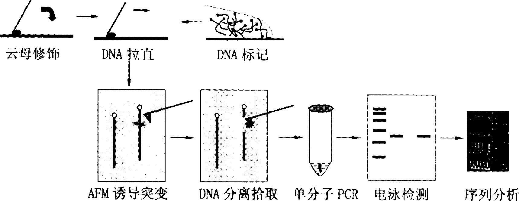
[0043] Such as figure 1 As shown, the positioning and detection of mechanically induced mutations and detection of pBR322 DNA by AFM include the following steps:

[0044] 1. Prepare a mica substrate modified with aminosilane (APTES), and modify the substrate with 3-amino-propyl-triethoxysilane (APTES) with a volume concentration of 1%. The specific steps are:

[0045] 1) Dilute APTES with water to a volume concentration of 1%, and pipette 20 μl and drop it on a clean parafilm;

[0046] 2) The newly dissociated mica (20mm×20mm) was blown off with an ear washing ball to remove debris, and covered on the APTES droplet;

[0047] 3) Modify at room temperature for 5 minutes, rinse with double distilled water 4 times, place on filter paper, and blow dry with clean nitrogen;

[0048] 4) The modified mica was baked in an oven at 120°C for 2 hours, and then irradiated with ultr...


PUM


Abstract

The method to induce monocular DNA directed mutation by atomic force microscope in biotechnology field comprises steps shown follow: (1) preparing mica substrate modified by aminosilane; (2) labelling the end of DNA sample; (3) straightening and preparing the labelled sample; (4) inducing mutation; (5) collecting and separating the induced DNA segment; (6) amplifying monocell; (7) detecting amplification by agarose gel electrophoresis; (8) sequenching sample DNA, and screening the mutated sample. The advantages of this invention include: precise location, high resolution, high efficiency, and simple operation.

Description


Claims


Application Information

Patent Timeline
Owner SHANGHAI JIAO TONG UNIV
Why Eureka
Try Eureka