Cutting member of mud digging system

A technology of cutting parts and mud system, which is applied in the direction of earth mover/shovel, mechanically driven excavator/dredger, construction, etc. The effect of simple connection and disconnection process

Inactive Publication Date: 2006-05-03
IHC HOLLAND NV
View PDF0 Cites 3 Cited by
  • Summary
  • Abstract
  • Description
  • Claims
  • Application Information

AI Technical Summary

Problems solved by technology

In fact, it is clear that the process of connecting and disconnecting pipes will cause various problems, such as improper sealing between pipes, adapters and teeth, which means that dirt, etc. can enter the connection area
This is highly undesirable as the connecting surfaces may be damaged

Method used


Image

  • Cutting member of mud digging system
  • Cutting member of mud digging system
  • Cutting member of mud digging system

Examples


Embodiment Construction

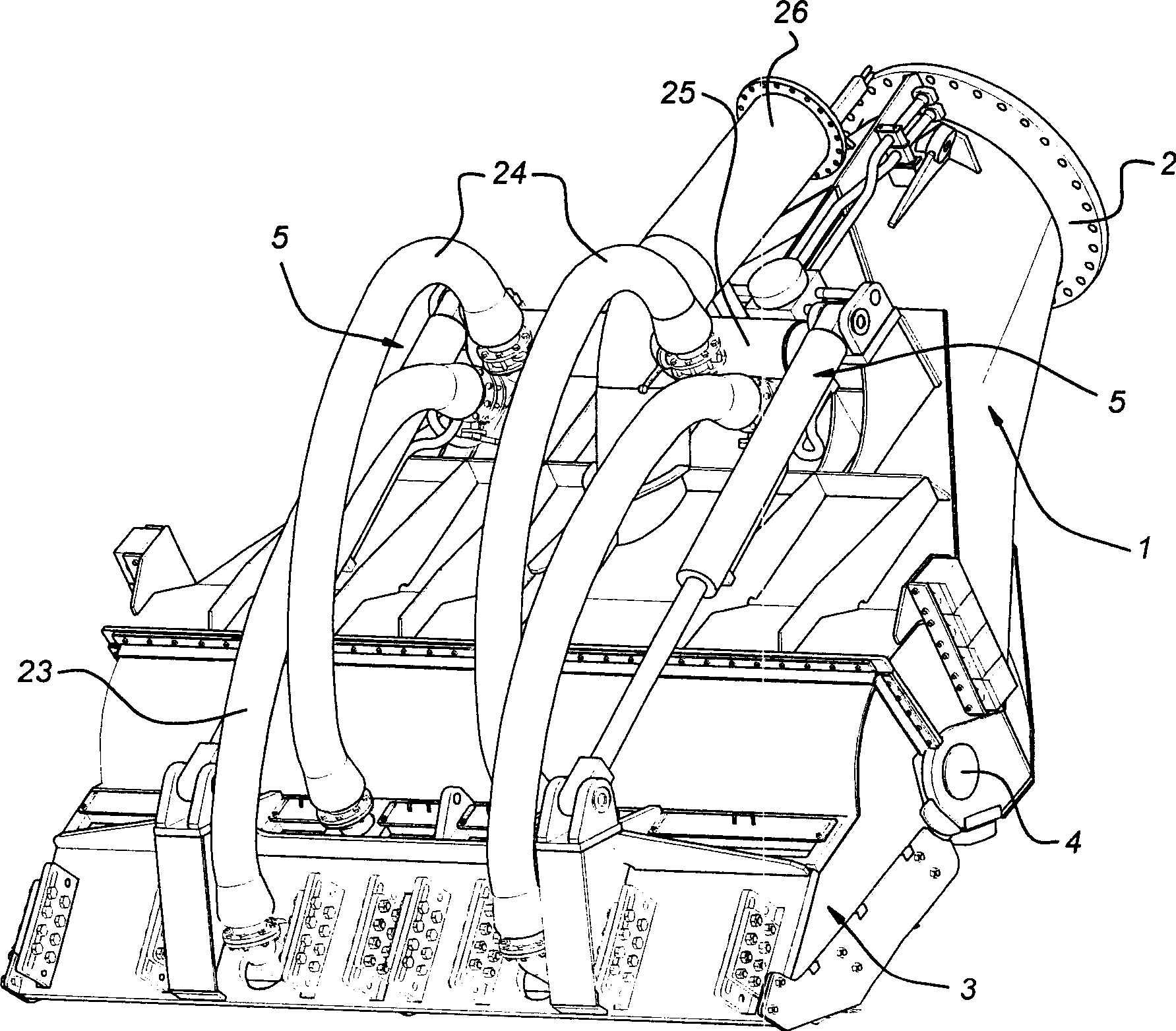
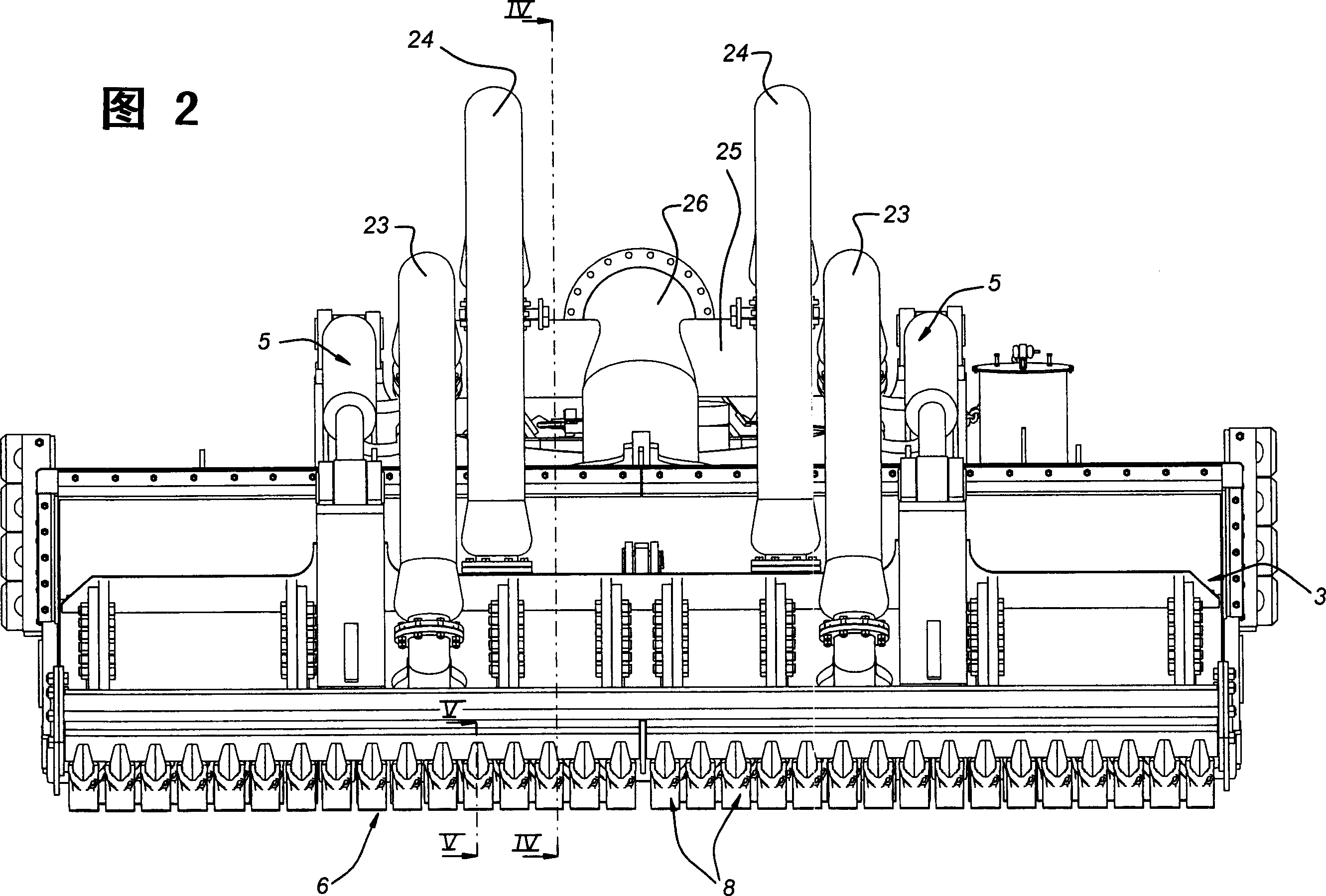
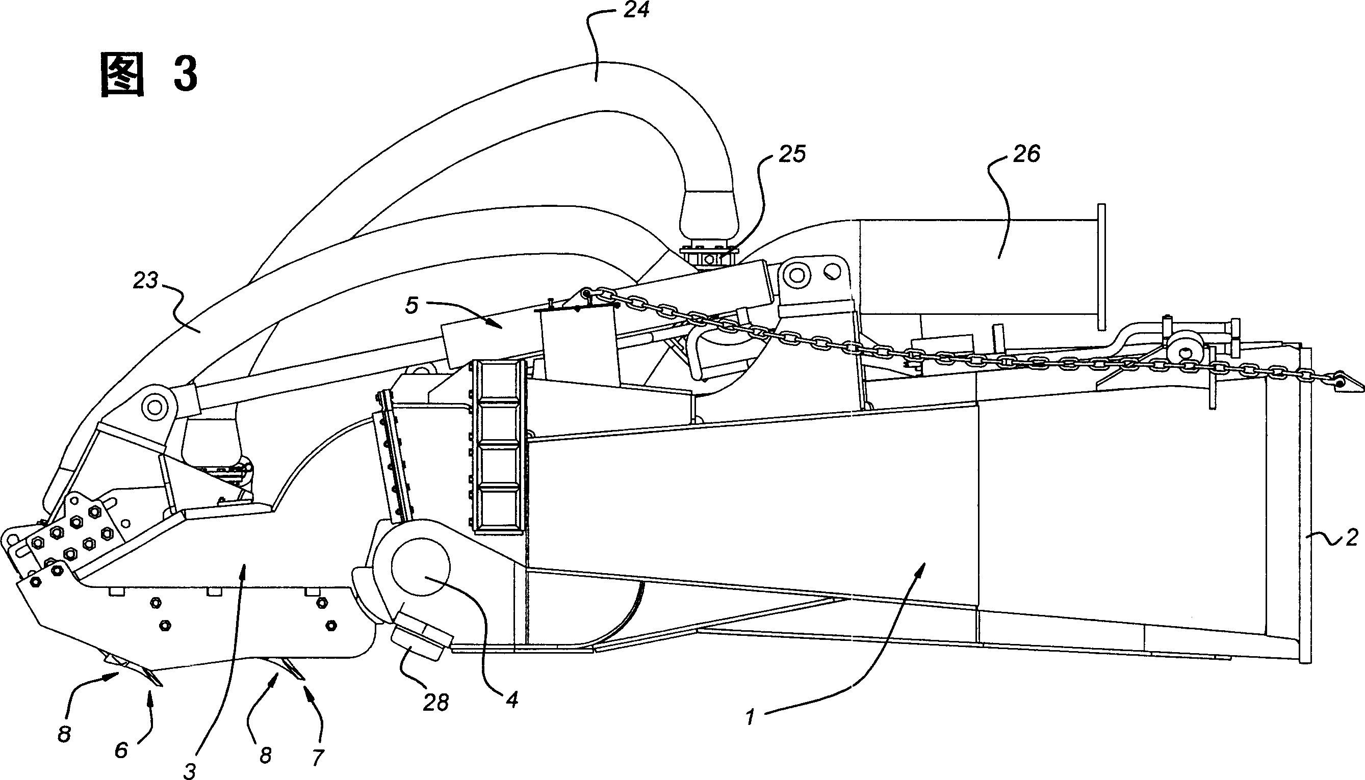
[0018] figure 1 The rake head shown in -3 includes a main body 1 with a mounting flange 2 at one end. Via the mounting flange 2, the drag head can be connected to a suction pipe and an excavation container (not shown in the figure). The other end of the body 1 carries a so-called visor 3 via a hinged connection 4 . The inclination direction of the shield plate 3 relative to the body 1 can be adjusted by a hydraulic piston / cylinder device 5 .

[0019] The visor 3 carries two rows 6, 7 of cutters 8 each with a nozzle 36 (other numbers of rows are also possible). These cutouts are enlarged and shown in Figure 5 middle. Each cutting element 8 comprises a cutting tooth 9 and a tooth holder 10 . The tooth holder 10 has a mounting part 11 which connects the tooth holder to a crossbar 12 on each row 6,7. Furthermore, each tooth 9 has a cavity 14 in which the prongs 13 of the mounting part 11 fit tightly. Axial displacement is prevented by pins (not shown) inserted into the too...


PUM


Abstract

The invention discloses a cutting element in the dredge system, which comprises the following parts: tooth within a cavity, tooth holder and water supply pipe, wherein the pipe supplies water flow to the near knife-edge; the tooth holder contains a cuspate inserted in the cavity tightly; the tooth holder contains a tooth holder channel and the tooth contains a tooth channel; one end of water supply pipe is matched in the tooth holder channel and the other end is matched in the tooth channel.

Description

technical field [0001] The invention relates to a cutting element for a dredging system, such as a rake head, comprising a tooth, a tooth seat and a pipe for supplying water flow near the cutting edge, the tooth is provided with a cavity, the tooth seat is provided with A prong that makes it fit snugly in the cavity. Background technique [0002] Such cutters are known. When a dredging system, such as a drag head, is moved across the bottom of a body of water, bottom material is dredged out by such cutting members. The excavated bottom material is collected in the main body under the influence of suitably oriented water jets and conveyed via a suction pipe into, for example, the funnel of a container. [0003] Additionally, water jets incorporated into the cutting elements aid in the cutting operation. Water is sent to the pipes in the cutting piece at a pressure which should be greater than the pressure of the surrounding water. These spouts also prevent the intrusion o...

Claims


Application Information

Patent Timeline
Patent Type & Authority Applications(China)
IPC IPC(8): E02F3/92
CPCE02F3/9262E02F9/2825
Inventor 赫里特·雅各布斯·彼得·费斯特格亚尔诺·克廷
Owner IHC HOLLAND NV
Why Eureka
Try Eureka