Main pipe construction method for laying tunnel structure and construction structure therof

A technology for tunnel structures and construction methods, which is applied in tunnels, tunnel linings, and infrastructure engineering, and can solve problems such as inconvenient operations, laying and connecting main pipelines, and difficult completion of tunnels

Inactive Publication Date: 2006-05-03
NTS ENC
View PDF0 Cites 8 Cited by
  • Summary
  • Abstract
  • Description
  • Claims
  • Application Information

AI Technical Summary

Problems solved by technology

[0006] However, when this method is forcibly pressed into the main pipeline, if the main pipeline is too long, it is impossible to continue to press in, which is inconvenient for subsequent operations, and the most important thing is that the method of pressing into the main pipeline for a long distance cannot be laid in a curved form. The main pipe, so it is difficult to complete the curved tunnel

Method used


Image

  • Main pipe construction method for laying tunnel structure and construction structure therof
  • Main pipe construction method for laying tunnel structure and construction structure therof
  • Main pipe construction method for laying tunnel structure and construction structure therof

Examples


Embodiment approach 1

[0024] Embodiment 1 of the present invention will refer to Figure 1a to Figure 3 Be explained. mainly includes:

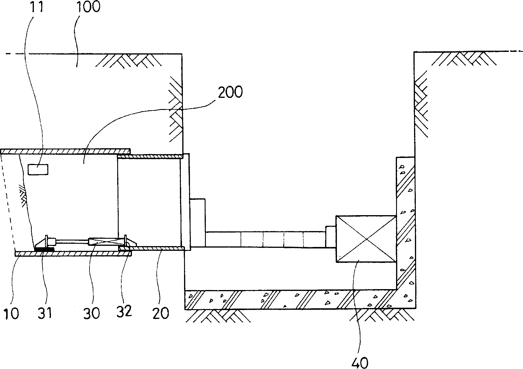
[0025] In order to lay various types of tunnel structures suitable for the topography and stratum conditions, wooden pipes 300 formed by combining a plurality of wooden boards 320 are laid for a long distance between both sides of steel pipes truncated at a certain length or between H beams 310 in the underground 100 round or angular main pipes. For this, as Figure 1a As shown, a certain number of reaction tables 31, 32 corresponding to each other are arranged at a certain interval on the inner side of the transmission pipe 10 and the main pipe 20, and the rod of the hydraulic / pneumatic cylinder 30 arranged between the reaction tables 31, 32 is advanced to utilize the hydraulic pressure. The jack 40 presses the transmission pipe 10 and the main pipeline 20 into the process A of the underground 100;

[0026] Such as Figure 1a Shown, in above-mentioned transfer...

Embodiment approach 2

[0031] Embodiment 2 of the present invention will refer to Figure 4 , other techniques will refer to figure 2 b to image 3 Be explained. mainly includes:

[0032] In order to lay a variety of tunnel structures suitable for terrain and stratum conditions, such as Figure 4 As shown, a certain number of reaction platforms 31, 32 corresponding to each other are arranged at a certain interval on the inner side of the transmission pipe 10 and the main pipeline 20, and the rod of the hydraulic / pneumatic cylinder 30 arranged between the reaction platforms 31, 32 is retreated. The hydraulic jack 40 presses the transmission pipe 10 and the main pipeline 20 into the underground 100 process A';

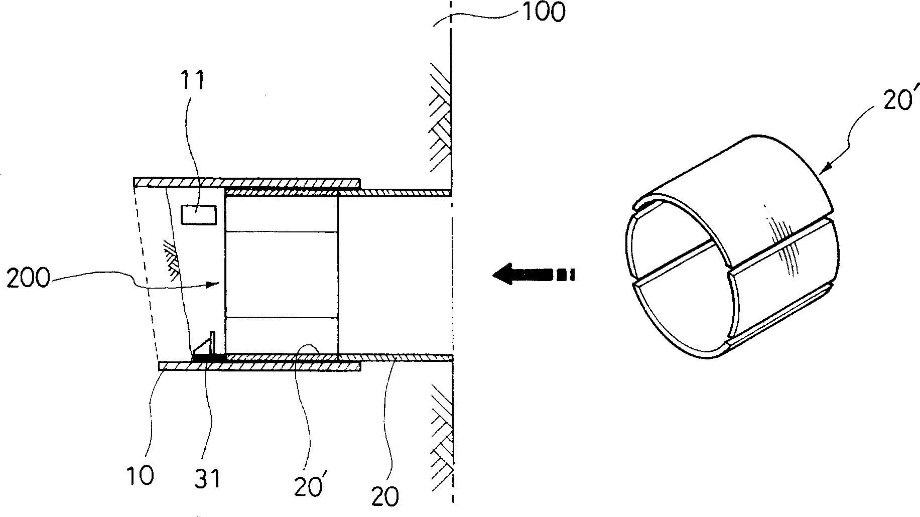
[0033] use Figure 1a Shown method, in above-mentioned transfer pipe 10 and main pipeline 20 press-in process, as Figure 1b As shown, through the input port 11 of the anti-collapse plate formed on the transmission pipe 10, the surrounding soil is dug out, and then the anti-collapse plat...

Embodiment approach 3

[0038] Embodiment 3 of the present invention will refer to Figure 5 , other techniques will refer to figure 2 b to image 3 Be explained. mainly includes:

[0039] In order to lay a variety of tunnel structures suitable for terrain and stratum conditions, such as Figure 5 As shown, the front reaction platform 31 is set inside the transmission pipe 10, so that the front end of the main pipe 20 is stuck here, and the transmission pipe 10 and the main pipe 20 are pressed into the underground 100 by the hydraulic jack 40. Process A";

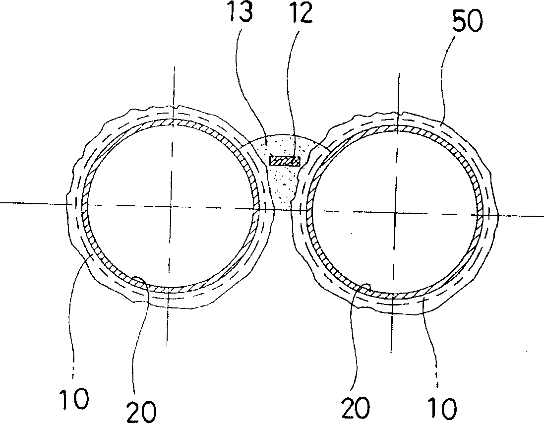
[0040] use Figure 1a Shown method, in above-mentioned transfer pipe 10 and main pipeline 20 press-in process, as Figure 1b As shown, through the input port 11 of the anti-collapse plate formed on the transmission pipe 10, the surrounding soil is dug out, and then the anti-collapse plate 12 is sequentially input and connected, and the mud is poured on the anti-collapse plate 12 to form a mud pouring part 13 to prevent the process of collapse...


PUM


Abstract

A method and a structure for constructing a main pipe installing a tunnel structure forming a tunnel are provided to quickly, easily, safely construct a number of main pipes under ground in straight or curved form. Using the said method and structure, the tunnel structure can bear tunnel external stress to the tunnel designed based on topography and stratum regardless of straight or curved tunnels, so that the designed tunnel can be easily and firmly constructed at short time using few manpower, equipment and facilities. The said method is composed of steps for press-fitting the guidance pipeand the main pipe under the ground; preventing landsliding; welding and connecting the main pipe in turn; propelling forward the guidance pipe; repeatedly the working of the main pipe and finally accomplishing tunnel construction.

Description

【Technical field】 [0001] The present invention relates to the construction method and construction structure of the main pipeline used for laying tunnel structures, and further description relates to the construction of straight or curved tunnels designed according to terrain and stratum conditions in order to be able to simply, firmly and perfectly complete the construction in a short period of time. A tunnel structure is a method and construction structure in which multiple main pipes are laid underground using a special method. 【Background technique】 [0002] Usually, in order to form a tunnel, tunnel structures must be laid to withstand the external stress of the tunnel. In the past, the tunnel was excavated to a certain depth, and then H beams or iron plates were used to erect the tunnel structures, and then repeat this process to form the tunnel. [0003] However, the previous methods of forming tunnels, whether straight or curved, are very complicated, prone to founda...

Claims


Application Information

Patent Timeline
Patent Type & Authority Applications(China)
IPC IPC(8): E21D9/00E21D11/10E21D11/38
CPCE02D3/12E21D9/001E21D9/06E21D11/15
Inventor 金正允
Owner NTS ENC
Why Eureka
Try Eureka