Shale gas pool hydraulic fracturing sand-adding technology

A hydraulic fracturing and shale gas reservoir technology, applied in the field of hydraulic fracturing, can solve problems such as large fluctuation range of construction pressure, incorrect sanding method, and difficulty in sanding, so as to eliminate the impact of formation blockage and ensure construction displacement Requirements, improve the effect of the overall amount of sand added

Inactive Publication Date: 2017-08-08
华美孚泰油气增产技术服务有限责任公司
View PDF7 Cites 7 Cited by
  • Summary
  • Abstract
  • Description
  • Claims
  • Application Information

AI Technical Summary

Problems solved by technology

[0004] In the process of hydraulic fracturing in shale gas reservoirs, compared with conventional oil and gas reservoirs, shale gas reservoirs have deeper burial depths, denser lithology, higher clay content, and lower permeability, resulting in increased construction pressure and difficulty in adding sand. On the one hand, the sand cannot be added to the formation or the amount of sand added is low, the concentration of sand on the surface of the fracture is low, and the sand is uneven, resulting in a decrease in the conductivity of the fracture, and even in some areas due to the lack of proppant, the fracture is completely closed, and no effective formation. support, thus greatly reducing the communication range and seepage capacity of shale oil and gas, resulting in the failure of hydraulic fracturing to achieve the expected stimulation effect
On the other hand, due to the incorrect method of adding sand or not conforming to the characteristics of the formation, the construction pressure fluctuates in a large range, and the pressure rises rapidly, resulting in overpressure, which affects the safety of construction and the normal progress of construction.

Method used


Image

  • Shale gas pool hydraulic fracturing sand-adding technology

Examples


Embodiment Construction

[0027] The present invention will be further described below in conjunction with the accompanying drawings.

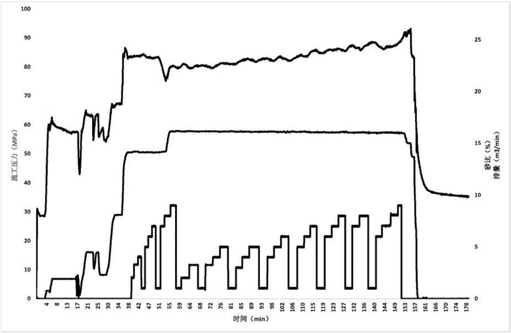
[0028] A schematic diagram of a shale gas reservoir hydraulic fracturing sand adding process of the present invention is as follows figure 1 shown.

[0029] A kind of shale gas reservoir hydraulic fracturing sand adding process of the present invention comprises the following stages:

[0030] (1) Pickling: Acid washing is performed on the perforation area and the near-well zone to remove the blockage around the perforation hole and the near-well zone. By acidizing and flushing the perforation area and the near-well zone, the blockage around the perforation hole and the near-well zone is removed to reduce the construction pressure. After the construction pressure is reduced, the step-up displacement is designed, and the construction displacement is changed from 2m according to the pressure change. 3 / min Stairs raised to 14m 3 / min or more, large-displacement hydrau...


PUM


Abstract

The invention discloses a shale gas pool hydraulic fracturing sand-adding technology, and belongs to the field of hydraulic fracturing. The shale gas pool hydraulic fracturing sand-adding technology comprises the following steps that (1) acid-pickling is conducted, and acid-pickling is conducted to an perforating area and a near-wellbore zone to remove blockages on perforations and the periphery of the near-wellbore zone; (2) silt is fractured, and sand-carrying fluid carries the silt to form fissure; (3) medium sand is fractured, and the sand-carrying fluid carries the medium sand to form the fissure; (4) coarse sand is fractured, and the sand-carrying fluid carries the coarse sand to fill the fissure of the near-wellbore zone; (5) the sand-carrying fluid is replaced, and ground high pressure pipe joints and the sand-carrying fluid in the wellbore are replaced into stratum to clear out the remaining sand in the wellbore; and (6) ending operation is conducted, a pressure dropping test is conducted, and the construction comes to an end. According to the shale gas pool hydraulic fracturing sand-adding technology, the whole sand-adding amount is improved, the construction pressure is smoother and steadier, the density of sand-paving is evener, and the fissure flow conductivity is effectively improved.

Description

technical field [0001] The invention belongs to the field of hydraulic fracturing, and relates to a sand adding process for hydraulic fracturing of shale gas reservoirs. Background technique [0002] In recent years, the shale gas revolution in the United States has had a major impact on the international natural gas market and the world's energy structure. The world's major resource countries have increased their efforts in shale gas exploration and development. During the "Twelfth Five-Year Plan" period, my country's shale gas exploration and development made a major breakthrough, becoming the first country outside North America to achieve large-scale commercial development. During the "13th Five-Year Plan" period, the new normal of my country's economic development promoted the continuous optimization and adjustment of the energy structure, and the demand for clean energy such as natural gas continued to increase. In 2015, the national shale gas demonstration area of ​​Si...

Claims


Application Information

Patent Timeline
Patent Type & Authority Applications(China)
IPC IPC(8): E21B43/267
CPCE21B43/267
Inventor 马收张志昂刘明明黄明铮杨保军乔廷立丛颜李奕涵
Owner 华美孚泰油气增产技术服务有限责任公司
Why Eureka
Try Eureka