

Method for determining metal film fatigue life in electro-mechanical coupling field
A metal film, fatigue life technology, used in the application of stable tension/pressure testing material strength, measuring devices, material analysis by electromagnetic means, etc. The contact between the film and the external circuit is unstable, so as to avoid the effect of stress constraint
- Summary
- Abstract
- Description
- Claims
- Application Information
AI Technical Summary
Problems solved by technology
Method used
Image

Examples
Embodiment 1
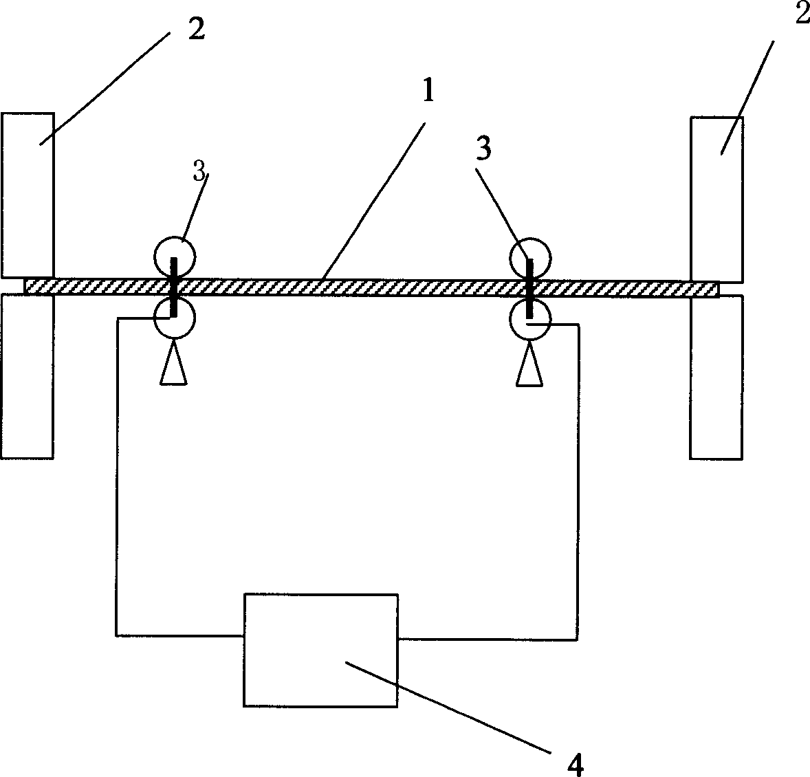
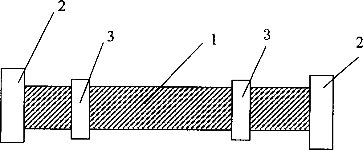
[0018] The polyimide flexible substrate is processed into a traditional tensile sample shape, the narrow and long area in the middle (20×6mm) is the effective working area of the sample, and the wide areas at both ends are the tensile clamping area. The metal Cu thin film was deposited on the effective working area by magnetron sputtering deposition method, with a thickness of 20 microns, and the deposition process parameters were: sputtering power 150W; sputtering bias -80V; background pressure 4.5×10 -3 Pa; working Ar pressure 1Pa. The sample is placed horizontally on the micro-tensile testing machine, the two ends of the sample are respectively clamped by the tensile chuck, the roller contact device is tightly in contact with the copper film, and the two rollers are respectively connected to the two poles of the current application device. form a current loop. Electrical and mechanical loads were applied simultaneously, with a voltage of 12V and a stress amplitude of 2-2...
Embodiment 2
[0020] The polyimide flexible substrate is processed into a traditional tensile sample shape, the narrow and long area in the middle (20×6mm) is the effective working area of the sample, and the wide areas at both ends are the tensile clamping area. The metal Al thin film was deposited on the effective working area by magnetron sputtering deposition method, with a thickness of 200 nm, and the deposition process parameters were: sputtering power 200W; sputtering bias -70V; background pressure 4.5×10 -3 Pa; working Ar pressure 1Pa. . The sample is placed horizontally on the micro-tensile testing machine, the two ends of the sample are respectively clamped by the tensile chuck, the roller-type contact device is tightly contacted with the aluminum film, and the two rollers are respectively connected to the two poles of the current application device. form a current loop. Electrical and mechanical loads were applied simultaneously, with a voltage of 6V and a stress amplitude of...
Embodiment 3
[0022] The polyimide flexible substrate is processed into a traditional tensile sample shape, the narrow and long area in the middle (20×6mm) is the effective working area of the sample, and the wide areas at both ends are the tensile clamping area. The metal Cu thin film was deposited on the effective working area by the magnetron sputtering deposition method, the thickness was 2.5 microns, and the deposition process parameters were: sputtering power 150W; sputtering bias -80V; background pressure 4.5×10 -3 Pa; working Ar pressure 1Pa. The sample is placed horizontally on the micro-tensile testing machine, the two ends of the sample are respectively clamped by the tensile chuck, the roller contact device is tightly in contact with the copper film, and the two rollers are respectively connected to the two poles of the current application device. form a current loop. Electrical and mechanical loads were applied simultaneously, with a voltage of 8V and a stress amplitude of 2...
PUM
| Property | Measurement | Unit |
|---|---|---|
| thickness | aaaaa | aaaaa |
| thickness | aaaaa | aaaaa |
| fatigue bending times | aaaaa | aaaaa |
Abstract
Description
Claims
Application Information