Surface flow controlled valve and screen

A technology of screen tube and controller, applied in the direction of production fluid, wellbore/well valve device, instrument, etc., can solve problems such as restriction of production well or injection well, and achieve the effect of reducing downhole intervention

Inactive Publication Date: 2006-05-03
SHELL INT RES MAATSCHAPPIJ BV
View PDF3 Cites 6 Cited by
  • Summary
  • Abstract
  • Description
  • Claims
  • Application Information

AI Technical Summary

Problems solved by technology

Often, existing modular systems can create undue constraints on production or injection wells due to their physical size and flow factors, especially when placed within conventional downhole screens
Additionally, existing systems are not ideal for detecting well-specific flow phenomena, while integrated screen systems provide reliable detection, testing, qualification and flow control

Method used


Image

  • Surface flow controlled valve and screen
  • Surface flow controlled valve and screen
  • Surface flow controlled valve and screen

Examples


Embodiment Construction

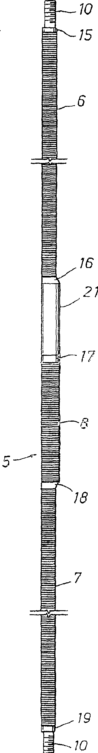
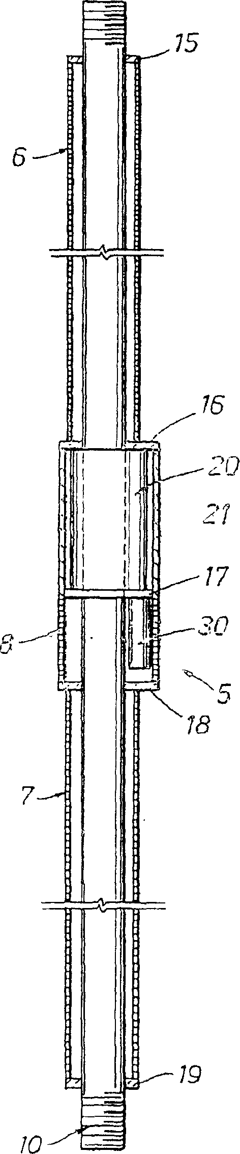
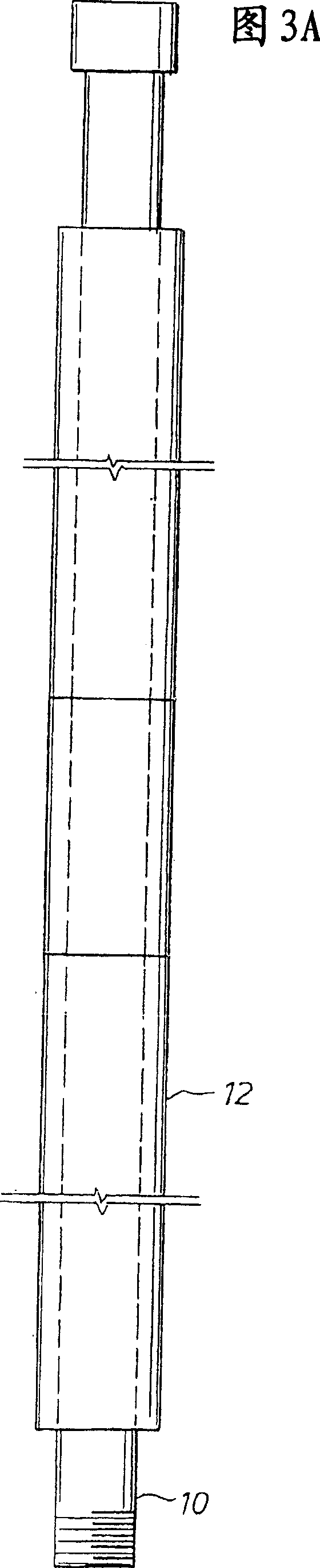
[0053] see figure 1 , which shows a side view of the adjustable downhole sand control screen 5 . The sand control screen 5 is composed of three parts, namely the upper screen 6 , the lower screen 7 and the valve screen 8 . Each of these screens can be constructed in a manner known to those skilled in the art. For example, if Figure 3B As shown, the screen can include a central pipe 10 , longitudinal fins 11 and a screen 12 . In this particular invention, the base tube 10 has no perforations to allow fluid to flow between the outside and the inside of the base tube. In this respect, the base pipe 10 described differs from production screens known in the art. The longitudinal ribs 11 are arranged around the outside of the central pipe 10 in the longitudinal direction. The screens 12 are then wrapped around the longitudinal fins 11 to define channels 13 between the central pipe 10 , adjacent longitudinal fins 11 and the screens 12 . Said channel 13 is the part between the ...


PUM


Abstract

An adjustable well screen assembly having a pipe which is connectable to a production pipe, wherein the pipe comprises a hole extending from the ID of the pipe to the OD of the pipe; a screen connected to the pipe adjacent the hole of the pipe; a valve connected to the pipe, wherein the valve controls fluid flow through the hole of the pipe; a valve motor mechanically connected to the valve, wherein the valve motor opens and closes the valve; and a valve controller communicatively connected to the valve motor, wherein the valve controller instructs the valve motor as to a configuration of the valve.

Description

[0001] related application [0002] This application is related to commonly assigned application WO / 03 / 023185A1. technical field [0003] The present invention relates to an adjustable downhole screen assembly for controlling the flow of fluid from a hydrocarbon containing formation into the production tubing of a hydrocarbon fluid production well. [0004] The invention also relates to a hydrocarbon fluid production well equipped with one or more downhole screen assemblies. Background technique [0005] Well completion techniques to expel solid particles produced by wellbore fluids are well known in the gravel packing art. [0006] The practice of constructing a wellbore that penetrates the formation often requires the placement of steel casings or other conduits within the wellbore. In some wellbore configurations, the casing is cemented within the wellbore by Portland cement in the annulus between the casing and the wellbore. The casing may be deployed at a depth throu...

Claims


Application Information

Patent Timeline
Patent Type & Authority Applications(China)
IPC IPC(8): E21B34/06E21B43/08E21B43/12G06F19/00G06F19/28G06Q10/00
CPCE21B43/12E21B43/08G16B50/00
Inventor 菲尔·费尔保罗·T·胡卡比蒂姆·迈克派克爱德华·E·舒米拉克二世戴维·R·史密斯乔治·黄国启
Owner SHELL INT RES MAATSCHAPPIJ BV
Why Eureka
Try Eureka