
Automatic crude oil demulsification and dehydration device, and its control method

A technology of demulsification device and dehydration device, which is applied in the directions of dehydration/demulsification regulation/control, immiscible liquid separation, liquid separation auxiliary equipment, etc. The effect of industrial automatic production

Inactive Publication Date: 2006-05-10
WEIHAI HAIHER TECH
View PDF4 Cites 9 Cited by
  • Summary
  • Abstract
  • Description
  • Claims
  • Application Information

AI Technical Summary

Problems solved by technology

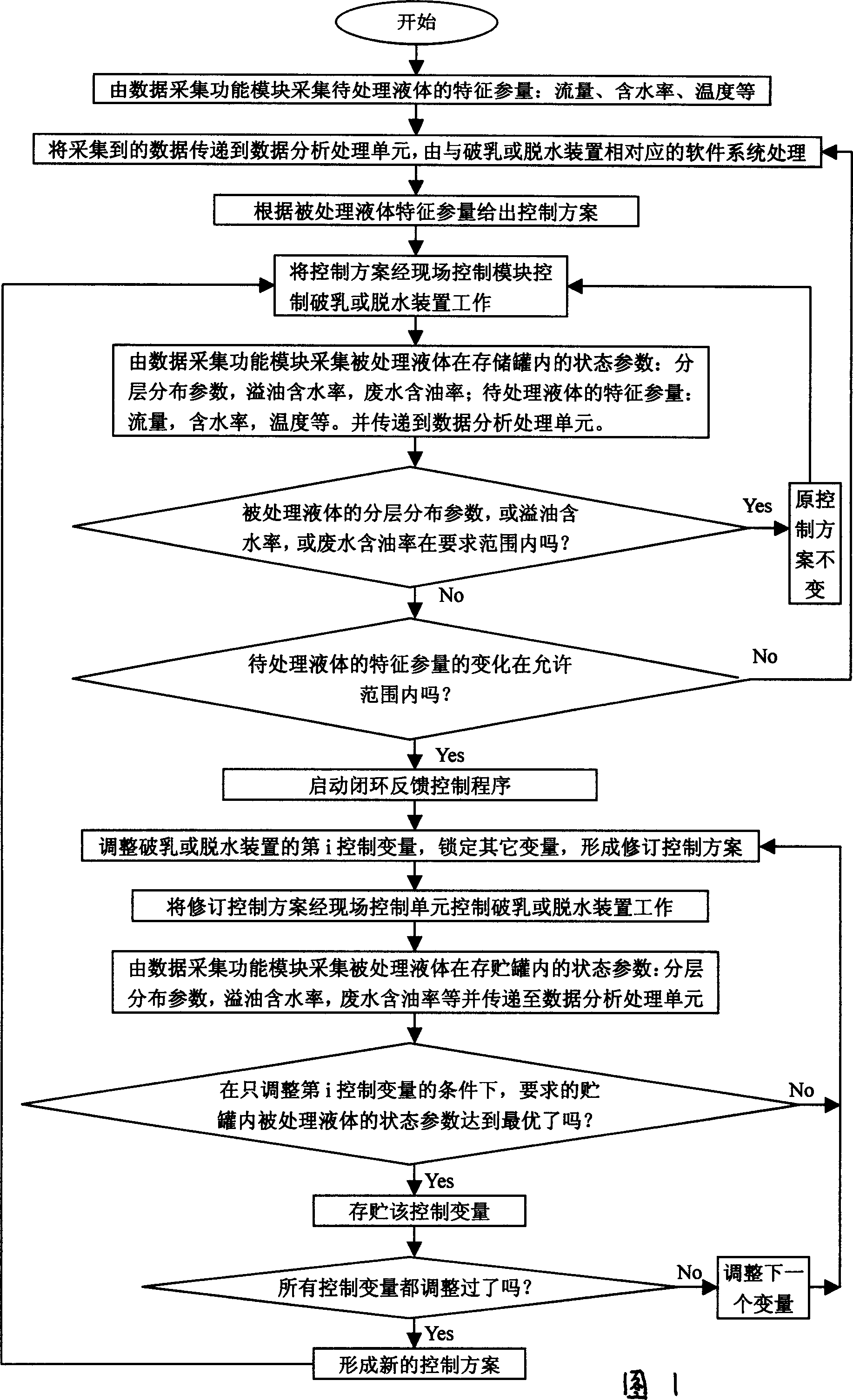
[0007] In order to solve the problem of demulsification and dehydration in the industrial production process, there are various methods and devices for demulsification and dehydration, which can only passive demulsification or dehydration, and cannot deal with the characteristic parameters (flow rate, composition, temperature, etc.) of the liquid to be treated and the device itself in real time. The change of working state can not guarantee the problem of automatic and stable operation of industrial production. The purpose of this invention is to provide a kind of crude oil automatic demulsification dehydration device and its control method. ) monitoring and the stratification status of the treated liquid in the mixed storage state, the monitoring of the water content of the spilled oil, the oil content of the drainage, etc., and automatically generate a set of solutions. When the characteristic parameters of the treatment liquid change or the demulsification or dehydration device When the working state of the machine drifts, the automatic control demulsification or dehydration device adjusts its working parameters to adapt to these changes, so that the device is in the best state and meets the needs of industrialized automatic production

Method used


Image

  • Automatic crude oil demulsification and dehydration device, and its control method
  • Automatic crude oil demulsification and dehydration device, and its control method
  • Automatic crude oil demulsification and dehydration device, and its control method

Examples


Embodiment 1

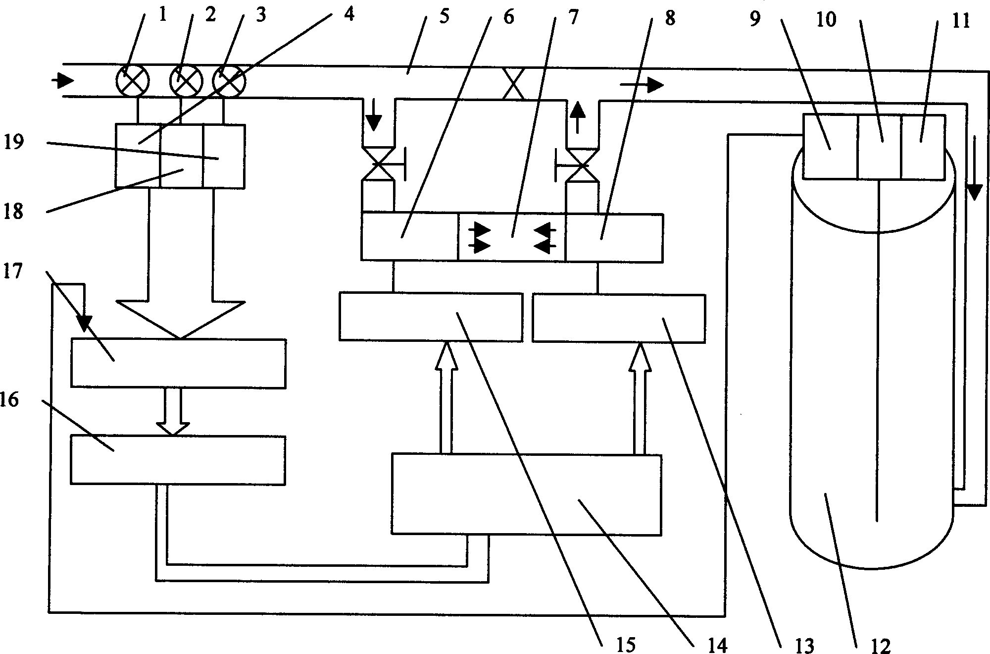
[0023] figure 1, figure 2 As shown, the demulsification device is connected between the crude oil input pipeline 5 and the storage tank 12. The demulsification device adopts an ultrasonic demulsification device. Composition, its structure is known to those of ordinary skill in the art, ultrasonic generator 15, ultrasonic generator 13 are electrically connected with data output control unit 14, and crude oil input pipeline 5 is provided with flow monitoring probe 1 and moisture content monitoring probe 2 , the temperature monitoring probe 3, the flow monitoring probe 1 and the moisture content monitoring probe 2, the temperature monitoring probe 3 respectively through the flow monitoring instrument 4 and the moisture content monitoring instrument 18, the temperature monitoring instrument 19 is electrically connected with the data acquisition unit 17, the storage tank 12 There are mixed storage medium stratification monitoring instrument 9 and oil spill water content monitoring ...

Embodiment 2

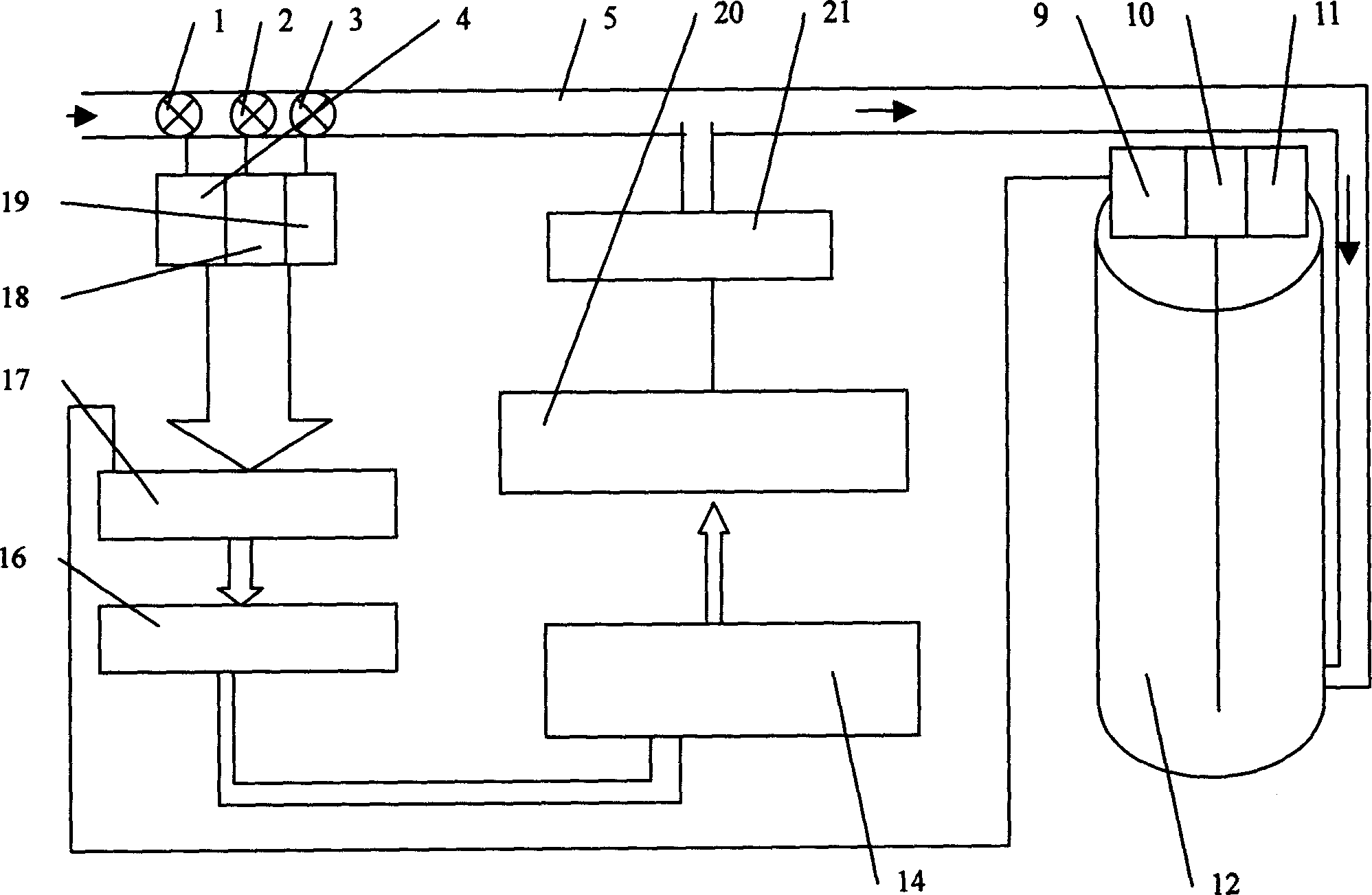
[0030] Embodiment two: the characteristic parameters of the liquid to be treated in the crude oil pipeline 5 can only collect one or any two of flow, water content, temperature (or a combination of parameters containing at least one of the above parameters), and flow monitoring corresponding to this Probe 1, moisture content monitoring probe 2, temperature monitoring probe 3 and flow monitor 4, moisture content monitoring instrument 18, temperature monitoring instrument 19 also only use one or any two. Similarly, the state parameters of the treated liquid in the storage tank 12 can also only collect one or any two of the oil-water layer distribution value, the water content of oil spill and the oil content of waste water (or a combination of parameters containing at least one of the above parameters) , mixed storage medium stratification condition monitor 9 and oil spill water content monitor 10, waste water oil content monitor 11 also just use one or any two thereupon. The co...

Embodiment 3

[0035] Figure 1, figure 2 As shown, the structure of the automatic demulsification device in this embodiment is the same as that in Embodiment 1.

[0036]The control method implemented in this embodiment is aimed at the situation that the characteristic parameters (flow, water content, temperature) of the liquid to be treated fluctuate greatly: the data acquisition unit 17 first passes through the flow monitor 4, the water content monitor 18, the temperature monitor 19 and The flow monitoring probe 1, the water content monitoring probe 2 and the temperature monitoring probe 3 connected thereto collect the flow rate, water content and temperature characteristic parameters of the liquid to be treated in the crude oil input pipeline 5, and the data acquisition unit 17 passes the received data through After sequence processing, it is converted into a digital signal convenient for system processing and transmission and passed to the data analysis and processing unit 16. The CPU of ...


PUM


Abstract

The invention relates the crude oil automatic demulsifying dehydration apparatus and its controlling means, comprising the following characters: setting the flow monitoring probe or moisture percentage monitoring probe or temperature monitoring probe in the crude oil input pipe, fixing the medium layered condition monitoring instrument or oil spilling moisture percentage monitoring instrument or waste water oil length monitoring instrument on the storage tank, monitoring probe and monitoring instrument connected with data acquisition unit, the data acquisition delivering the characteristic parameter of pretreatment fluid in the oil pipeline and state parameter of treatment fluid in the storage tank to analysis of data processing unit by data line, the CPU of analysis of data processing unit dealing with the datas and exporting digit signal to data out control unit, and the electrical signal exported by data out control unit to control the demulsification apparatus.

Description

technical field [0001] The invention relates to a method and device for separating oil and water by physical or chemical methods in the crude oil production process, in particular to an automatic crude oil demulsification device and a control method thereof. Background technique [0002] In the production and processing of crude oil, an important process is oil-water separation, or dehydration. The key to dehydration is to try to break the oil-water emulsion structure that is closely combined and has different specifications. This process is called Demulsification, there are many ways of demulsification, such as: chemical demulsification, ultrasonic demulsification, etc., and then try to separate the mixed oil or water particles from each other, coagulate each other, and finally realize the separation of oil and water, which is called demulsification. Crude oil is dehydrated, and there are many dehydration methods, such as electrostatic dehydration, heating and sedimentation...

Claims


Application Information

Patent Timeline
Patent Type & Authority Applications(China)
IPC IPC(8): C10G33/08B01D17/04B01D17/12
Inventor 王其明李春和王福文周振华唐建平刘安勋
Owner WEIHAI HAIHER TECH
Learn More