
Device and method for determining vehicle speed sensor fault for electronic coutrol system

A technology for electronic control systems and sensor failures, applied in control devices, control/regulation systems, measuring devices, etc., can solve the problems of not setting gear position sensors, control operation miscontrol, not setting throttle position sensors, etc.

Inactive Publication Date: 2006-05-24
MANDO CORP
View PDF0 Cites 17 Cited by
  • Summary
  • Abstract
  • Description
  • Claims
  • Application Information

AI Technical Summary

Problems solved by technology

[0006] However, some diesel vehicles or systems do not have a throttle position sensor
In this case, because the electronic control system did not use the information from the throttle position sensor to determine the presence or absence of a vehicle speed sensor fault, it was incorrect to determine the presence or absence of a vehicle speed sensor fault, which resulted in Miscontrol in control operation of information electronic control system
[0007] Additionally, in some vehicles or systems, there may not be a gear position sensor provided to provide gear position information
In this case, because the electronic control system does not use the gear position information to determine whether the vehicle speed sensor failure exists, the determination of the presence or absence of the vehicle sensor failure is incorrect, which results in the electronic control system using the vehicle speed information Miscontrol in control operation

Method used


Image

  • Device and method for determining vehicle speed sensor fault for electronic coutrol system
  • Device and method for determining vehicle speed sensor fault for electronic coutrol system

Examples


Embodiment Construction

[0015] Now, preferred embodiments of the present invention will be described in detail with reference to the accompanying drawings.

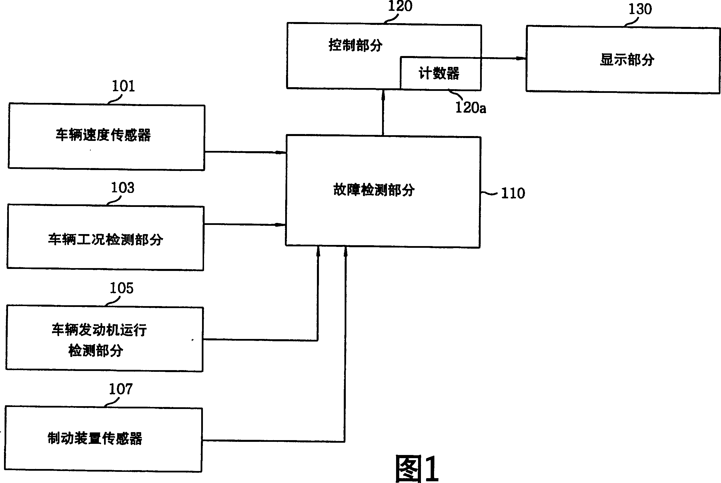
[0016] Referring to FIG. 1 , there is provided a block diagram of a vehicle speed sensor failure detection apparatus for an electronic control system according to a preferred embodiment of the present invention. As shown in Figure 1, the vehicle speed sensor fault detection device for determining the fault of the vehicle speed sensor 101 includes a vehicle operating condition detection part 103, a vehicle engine running detection part 105, a braking device sensor 107, a fault detection part 110, a control part 120 and display part 130.

[0017] The vehicle speed sensor 101 detects the vehicle speed, generates a vehicle speed information signal representing vehicle speed information, and transmits it to the fault detection part 110 .

[0018] The vehicle engine operation detection part 105 determines whether the vehicle engine is in an ON or OFF...


PUM


Abstract

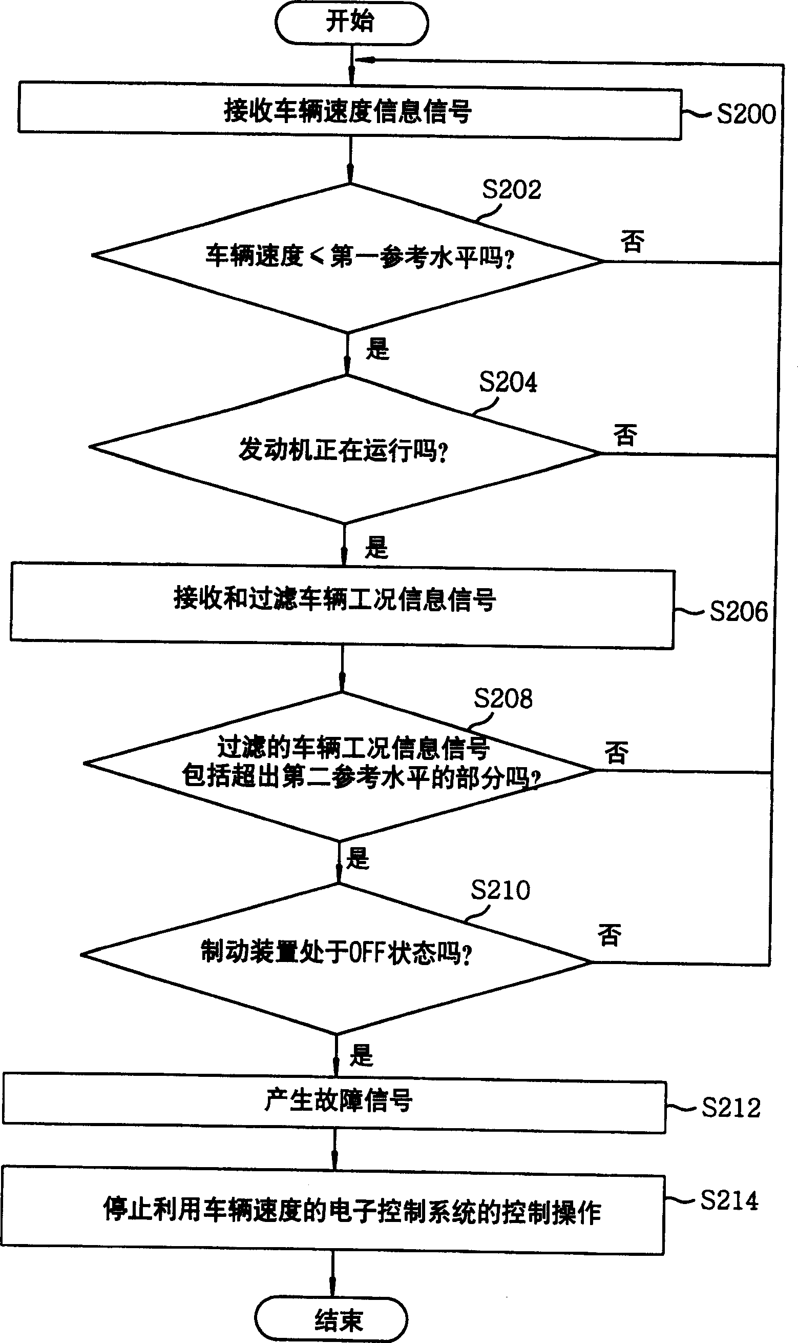
The detector set is in use for an electric control system. The electric control system possesses a speed sensor for vehicle. The speed sensor is in use for generating signal of speed information of vehicle. The detector set includes part for detecting operating condition of vehicle, sensor of brake gear, and part of fault detection. A fault signal is generated from the part of fault detection when following condition is met: if speed information of vehicle generated from the speed sensor for vehicle is smaller than or equal to a speed reference level stored in the part of fault detection, as well as information signal of operating condition generated at a prearranged time period exceeds reference level of operating condition stored in the part of fault detection, and brake gear is in OFF state.

Description

technical field [0001] The present invention relates to an electronic control system for a vehicle; and more particularly, to a vehicle speed sensor failure detection device and method for an electronic control system capable of avoiding electronic control failures caused by a failure of the vehicle speed sensor System miscontrol. Background technique [0002] In general, an electronic control system for a vehicle receives information from various sensors, processes the received information, and drives corresponding circuits and / or brakes so that appropriate control operations can be performed. There are various electronic control systems such as electronically controlled suspension, electronically controlled steering, ABS (anti-lock braking system), TCS (traction control system), ESP (electronic stability program), and the like. [0003] Specifically, in the electronic control system, since the means for determining the vehicle running state or the road surface condition o...

Claims


Application Information

Patent Timeline
IPC IPC(8): G01M17/007B60K31/00
Inventor 金完鎰
Owner MANDO CORP
Learn More