Method for avoiding interference in pulse signal and terminal applicable thereto

A pulse signal and pulse technology, applied in the interference avoidance method and its applicable terminal field, can solve problems such as MCU chip chip malfunction, signal malfunction, signal attenuation and distortion, and achieve the effect of avoiding attenuation or distortion and avoiding miscontrol

Inactive Publication Date: 2014-03-26
TCL CHINA STAR OPTOELECTRONICS TECH CO LTD
View PDF4 Cites 0 Cited by
  • Summary
  • Abstract
  • Description
  • Claims
  • Application Information

AI Technical Summary

Problems solved by technology

[0003] However, during the transmission process of the pulse signal from the pulse signal sending end to the pulse signal receiving end, it is susceptible to interference from low-frequency interference signals generated by other power devices in the pulse signal transmission line, and the interference signals crosstalk into the Vsync signal and the CS signal Finally, it will cause the MCU chip or the LED constant current drive IC chip to malfunction, because the Vsync signal and the CS signal themselves are also very short pulse signals. If the traditional R and C line filters are used, the attenuation of the Vsync signal and the CS signal will be caused. , distortion, will also cause signal malfunction (for example, malfunction of LED backlight control circuit)

Method used


Image

  • Method for avoiding interference in pulse signal and terminal applicable thereto
  • Method for avoiding interference in pulse signal and terminal applicable thereto
  • Method for avoiding interference in pulse signal and terminal applicable thereto

Examples


Embodiment Construction

[0022] It should be understood that the specific embodiments described here are only used to explain the present invention, not to limit the present invention.

[0023] It should be noted that the following embodiments are all described by taking "the pulse signal for controlling the LED backlight" as an example. Those skilled in the art should know that the following technical solutions for "the pulse signal for controlling the LED backlight" are also applicable As for other applicable high-frequency pulse signals, details will not be described here.

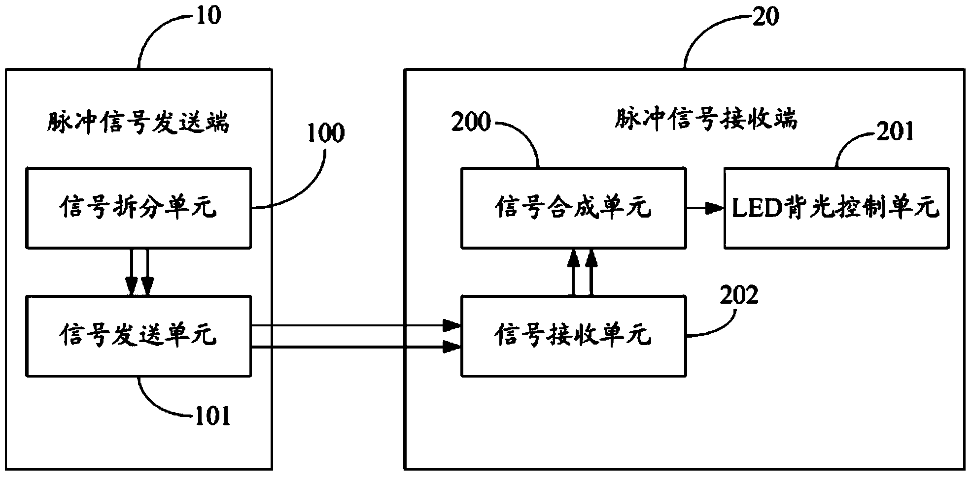
[0024] Such as figure 1 Shown is a hardware architecture diagram of a preferred embodiment of the pulse signal interference avoidance system of the present invention. The system includes a pulse signal sending end 10, and a pulse signal receiving end 20 communicatively connected with the pulse signal sending end 10 through a parallel pulse signal channel. The function of the parallel pulse signal channels (for example, two pu...


PUM


Abstract

The invention provides a method for avoiding the interference in a pulse signal. According to the method, the pulse signal is divided into two parallel sub pulse signals before being transmitted, wherein the two parallel sub pulse signals can be combined through subtraction, and then the pulse signal is restored; in the parallel transmission process of the two parallel sub pulse signals, interferences borne by both the sub pulse signals are almost the same; then, an interference signal is offset after the two parallel sub pulse signals are merged through subtraction; lastly, the merged pulse signal no longer carries the interference signal. As a result, false control caused by a crosstalk signal carried by the pulse signal in the transmission process is effectively avoided; meanwhile, signal false control caused by attenuation or distortion of the pulse signal in a traditional filtering method is effectively avoided. The invention further provides a terminal applicable to the method.

Description

technical field [0001] The invention relates to a pulse signal processing technology, in particular to a pulse signal interference avoidance method and an applicable terminal. Background technique [0002] The synchronous signal Vsync of the liquid crystal display screen, and the chip select signal CS in the SPI (Serial Peripheral Interface, Serial Peripheral Interface) protocol are all low-frequency pulse signals, and the frequency is generally 60Hz or 120Hz. These two pulse signals pass through a single The pulse signal channel (signal line) enters the MCU (Micro Control Unit, micro control unit) chip, or the LED constant current drive IC (Integrated Circuit, integrated circuit) chip that supports the SPI protocol, and the MCU chip and IC chip detect the After the rising edge or falling edge of the pulse signal, the relevant information in the data signal Data starts to be executed, and corresponding control operations are performed (for example, controlling the brightness...

Claims


Application Information

Patent Timeline
Patent Type & Authority Applications(China)
IPC IPC(8): H04L5/00
CPCH04J11/0023H04B1/719
Inventor 张华张先明
Owner TCL CHINA STAR OPTOELECTRONICS TECH CO LTD
Why Eureka
Try Eureka