
Electric rotating machine

A technology for rotating electric machines and winding parts, which is applied in the direction of electrical components, electromechanical devices, electric components, etc., and can solve problems such as size increase

Inactive Publication Date: 2006-05-31
MITSUBISHI ELECTRIC CORP
View PDF1 Cites 6 Cited by
  • Summary
  • Abstract
  • Description
  • Claims
  • Application Information

AI Technical Summary

Problems solved by technology

[0003] However, in this device, since the two sets of stators are arranged in the axial direction of the shaft, the dimension in the axial direction increases, and there is a problem of overall enlargement.

Method used


Image

  • Electric rotating machine
  • Electric rotating machine
  • Electric rotating machine

Examples


Embodiment Construction

[0017] Hereinafter, preferred embodiments of the present invention will be described with reference to the drawings. However, the same reference numerals will be assigned to the same and equivalent members or locations in the respective embodiments for description.

[0018] Embodiment 1

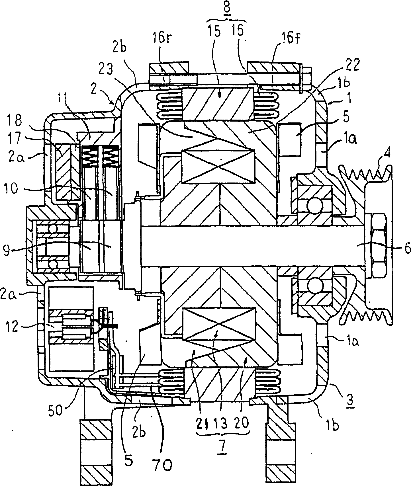
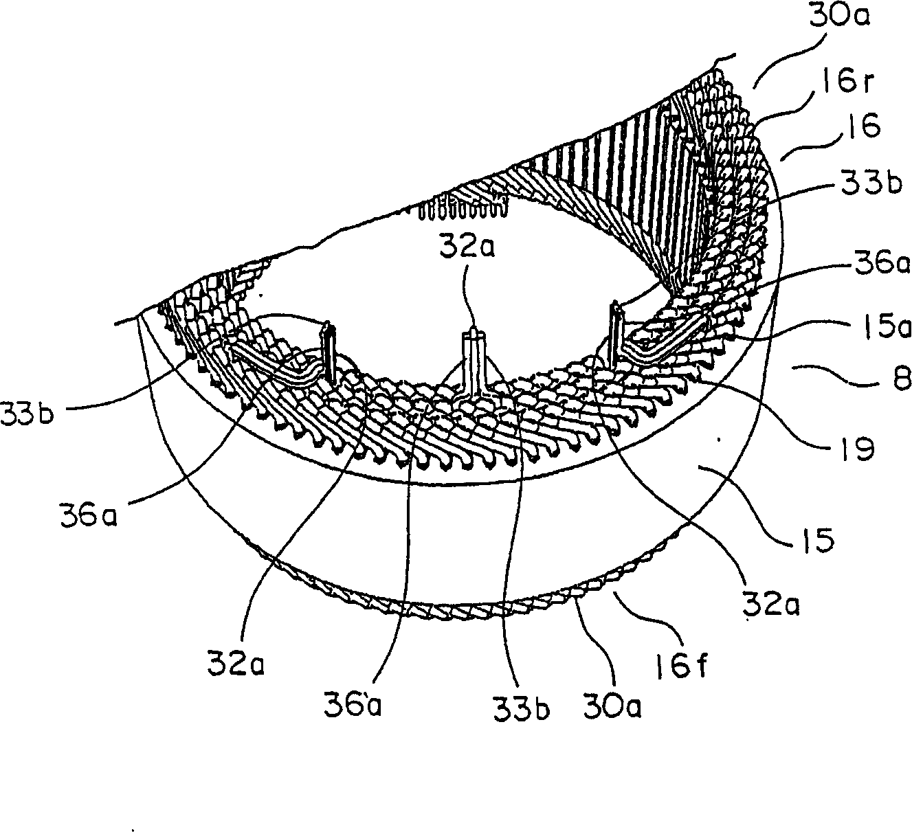
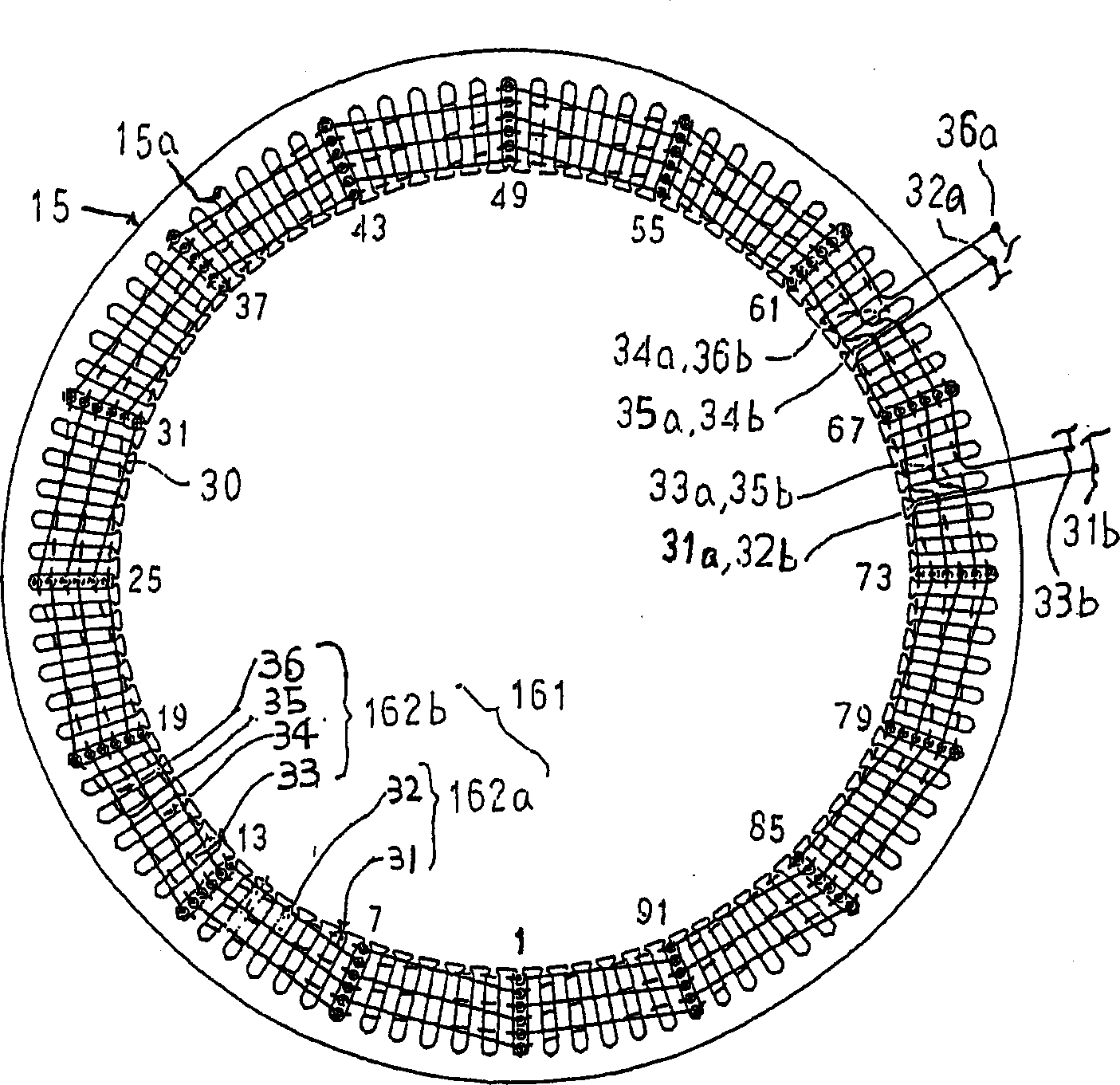
[0019] figure 1 is a cross-sectional view showing the structure of the vehicle alternator according to Embodiment 1 of the present invention, figure 2 yes means figure 1 A partial perspective view of the stator, image 3 yes means figure 1 The wiring diagram of the wiring state of 1 phase of the stator winding 16.

[0020] In this vehicle generator, a Landler type rotor 7 is rotatably provided via a shaft 6 in a housing 3 composed of an aluminum front bracket 1 and a rear bracket 2 . On the outer peripheral side of the rotor 7 acting as a magnetic field, a stator 8 acting as an armature is fixedly provided on the inner wall surface of the housing 3 . The shaft 6 is rotatably supported...


PUM


Abstract

An electric rotating machine comprising a first three-phase Y- mixed winding and a second Y- mixed winding wound around a stator core having a plurality slots. A first -U winding section and a first Y-U winding section are contained in the same slot, a first -V winding section and a first Y-V winding section are contained in the same slot, and a first -W winding section and a first Y-W winding section are contained in the same slot. A second -U winding section and a second Y-U winding section are contained in the same slot, a second -V winding section and a second Y-V winding section are contained in the same slot, and a second -W winding section and a second Y-W winding section are contained in the same slot.

Description

(1) Technical field [0001] The present invention relates to, for example, a rotating electrical machine driven by an internal combustion engine and mounted on cars, trucks, and the like. (2) Background technology [0002] In recent years, in vehicle alternators, it is necessary to increase the power generation output as the vehicle load increases. As a device for realizing the increase in power generation output, for example, Japanese Patent Laid-Open No. 5-308751 discloses a device with 2 A vehicle alternator with independent 3-phase stator windings. [0003] However, in this device, since the two sets of stators are arranged in the axial direction of the shaft, the dimension in the axial direction increases, and there is a problem of an overall increase in size. (3) Contents of the invention [0004] In order to solve the above-mentioned problems, an object of the present invention is to provide a rotating electrical machine capable of achieving a small size while ensur...

Claims


Application Information

Patent Timeline
Patent Type & Authority Applications(China)
IPC IPC(8): H02K3/04H02K3/28H02K3/50
CPCH02K3/28H02K3/505
Inventor 柏原利昭冈本省吾秋田裕之
Owner MITSUBISHI ELECTRIC CORP
Learn More