
Transformer

A technology of transformers and insulating tapes, applied in transformer/inductor components, transformer/inductor coils/windings/connections, coils, etc., can solve the problems of large transformer size, increased production cost, long time, etc., to achieve small The effect of transformer size, increased production cost, and increased occupancy

Inactive Publication Date: 2006-06-07
TDK CORP
View PDF0 Cites 3 Cited by
  • Summary
  • Abstract
  • Description
  • Claims
  • Application Information

AI Technical Summary

Problems solved by technology

[0005] However, in the first insulation structure, although insulating tapes are used to insulate adjacent coils of different polarities from each other, isolation tapes must also be provided on the end faces of the coils to ensure the creepage distance or space distance required by safety standards, As a result, the part where the coil cannot be set
As a result, the occupancy ratio of the coil in the bobbin becomes lower, resulting in a larger transformer size
[0006] Likewise, the second insulation structure based on the divided bobbin, as in the case of the first insulation structure, also requires a portion where coils cannot be placed, so that the occupancy ratio of the coils in the bobbin becomes low, resulting in a larger transformer size
[0007] On the other hand, although the third insulation structure based on resin molding does not have the disadvantage of larger transformer size in the first or second insulation structure, it requires special equipment in the transformer production process, and it also takes a long time to process. Resin cures, causing an increase in production costs
[0008] On the other hand, the above-mentioned prepreg tape is used in the structure disclosed in JP-A No. 9-330826, but this structure does not guarantee the primary coil and the secondary coil or the high voltage coil and the low voltage coil required by the safety standard. Deficiencies in creepage distances or spatial distances between coils

Method used


Image

  • Transformer
  • Transformer
  • Transformer

Examples


Embodiment Construction

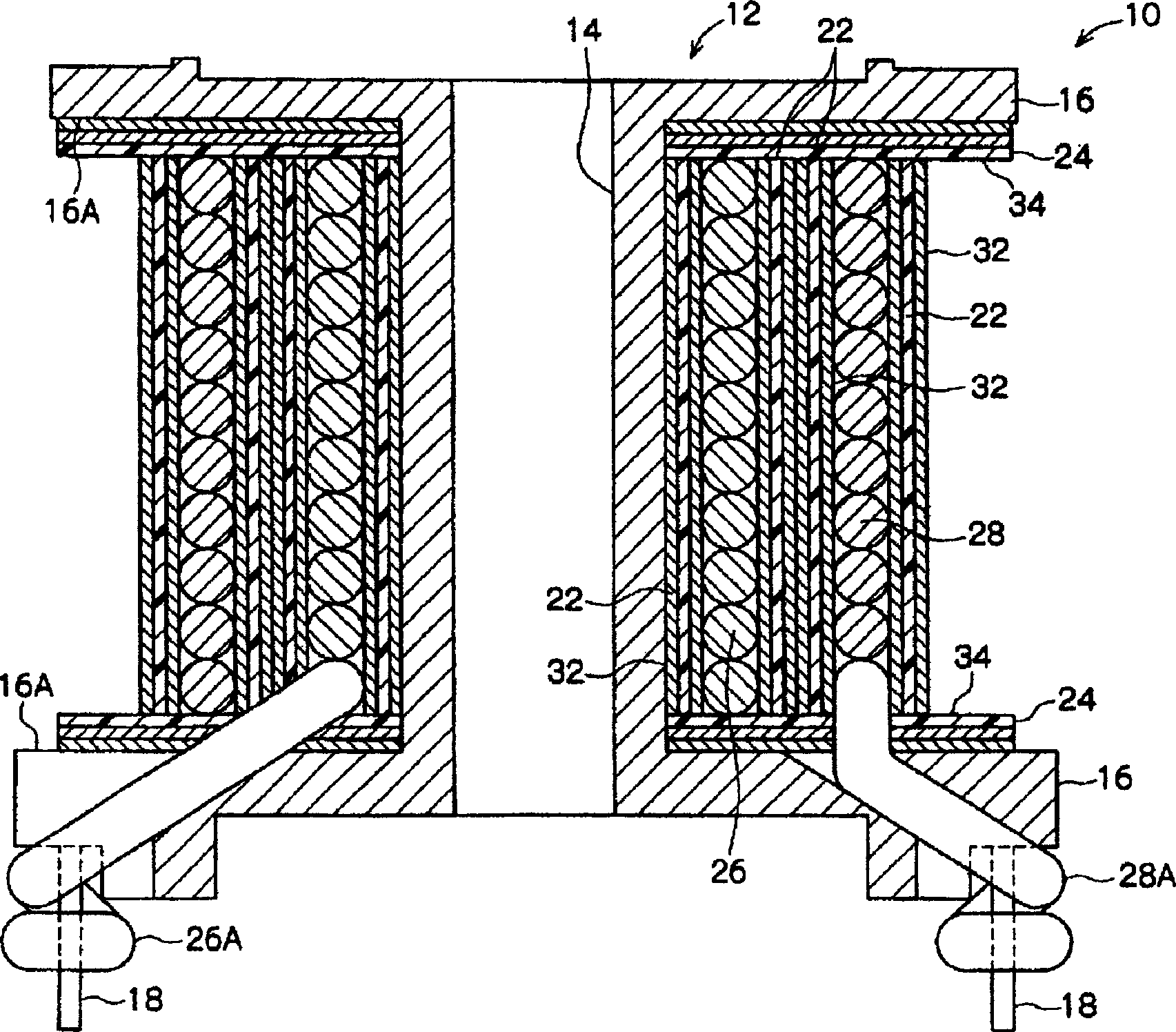
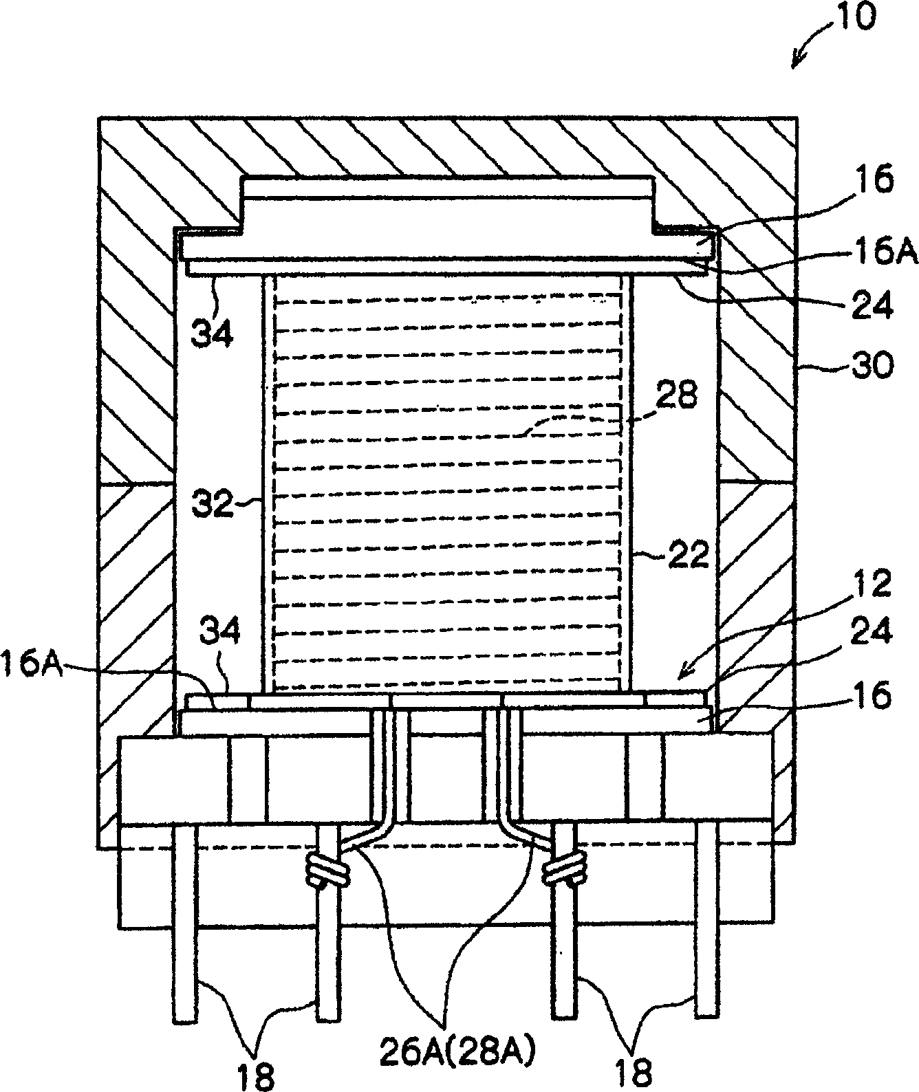
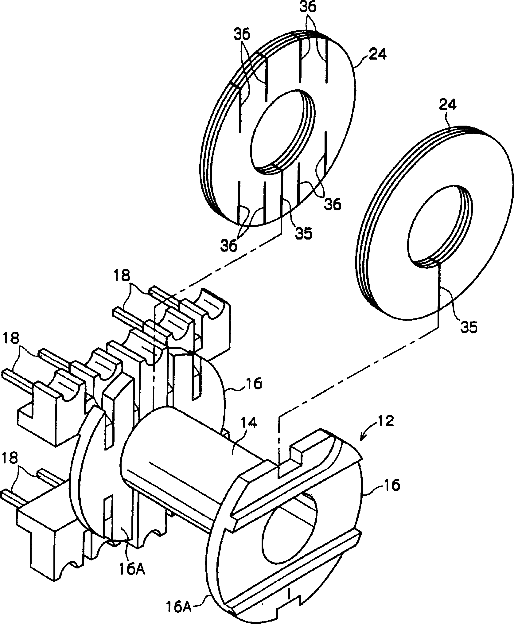
[0030] below, in Figure 1 to Figure 5 Embodiments of the transformer of the present invention are shown in and described with reference to these drawings. Such as Figure 1 to Figure 3 As shown, the bobbin 12 of the transformer 10 of the present embodiment is provided with a cylindrical bobbin 14 and a pair of flanges 16 formed at both ends of the bobbin 14 . One of the flanges 16 is provided with a plurality of terminals 18 , and the base ends of the terminals 18 are embedded in the flange 16 .

[0031] Such as figure 1 As shown, on the outer periphery of the bobbin 14, there is provided an insulating layer 32 formed by thermally curing the interlayer insulating prepreg tape constituting the first insulating tape. The primary coil 26 is wound on the outer circumference side of the insulating layer 32 , and the secondary coil 28 is wound on the outer circumference of the primary coil 26 . Further, lead wires 26A, 28A at both ends of these primary coils and secondary coils...


PUM

PropertyMeasurementUnit
lengthaaaaaaaaaa
lengthaaaaaaaaaa
lengthaaaaaaaaaa

Abstract

The invention discloses a transformer, wherein a pair of flanges (16) are formed at both ends of a bobbin (14) of a bobbin (12), and a heat-cured interlayer insulating prepreg tape ( 22) An insulating layer (32) is formed. A primary coil (26) is wound around the periphery of the insulating layer (32), and a secondary coil (28) is wound around the periphery of the primary coil (26). Insulating layers (32) are provided between the primary coil (26) and the secondary coil (28) and on the outer circumference of the secondary coil (28). On the surfaces (16A) facing each other of the pair of flanges (16), an insulating layer (34) formed by a heat-cured inner wall insulating prepreg tape (24) is provided, and this insulating layer (32 and 34) has mutual connected structure.

Description

technical field [0001] The present invention relates to a transformer capable of achieving a compact structure without increasing production cost by increasing the coil occupancy ratio in a winding frame, and, more particularly, to a transformer for insulation using prepreg tape (prepreg tape) the transformer. Background technique [0002] In transformers used in power supplies such as switching regulators, the insulation structures in the prior art are generally classified into the following three types, which can be properly selected according to the application or required performance. [0003] The first type of insulating structure is a tape insulating structure. In this structure, two coils respectively circumferentially wound on the bobbin are insulated from each other by means of an insulating tape also circumferentially wound on the bobbin. [0004] The second insulation structure is based on separate coil formers. In this structure, flanges are also provided insi...

Claims


Application Information

Patent Timeline
Patent Type & Authority Applications(China)
IPC IPC(8): H01F27/28H01F27/32
CPCH01F27/2823H01F27/323H01F27/324H01F2005/043
Inventor 北原觉金子滋
Owner TDK CORP
Learn More