Connection structure of plastic packaged motor stator iron core

A connection structure, stator core technology, applied in the direction of magnetic circuit shape/style/structure, magnetic circuit static parts, etc., can solve the problems of poor concentricity of the stator, waste of man-hours, and affect the performance of the motor, so as to improve performance and reduce The effect of simple production cost and manufacturing process

Inactive Publication Date: 2006-06-07
LG ELECTRONICS (TIANJIN) APPLIANCES CO LTD
View PDF0 Cites 1 Cited by
  • Summary
  • Abstract
  • Description
  • Claims
  • Application Information

AI Technical Summary

Problems solved by technology

[0007] However, using the above-mentioned welding method to make the motor stator, firstly, it is a waste of man-hours, and secondly, it is easy to cause poor concentricity of the stator during welding, thereby affecting the performance of the motor

Method used


Image

  • Connection structure of plastic packaged motor stator iron core
  • Connection structure of plastic packaged motor stator iron core

Examples


Embodiment Construction

[0020] The connection structure of the stator core of the plastic-encapsulated motor according to the present invention will be described in detail below with reference to the accompanying drawings and specific embodiments.

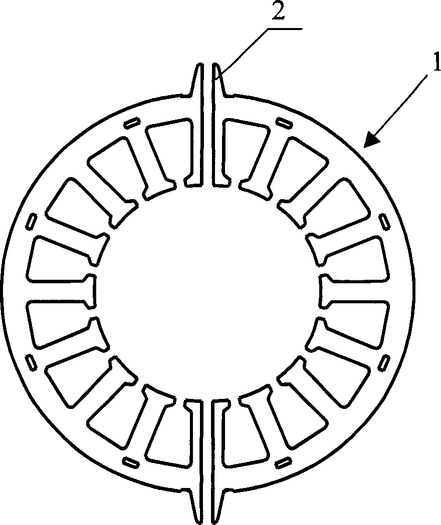
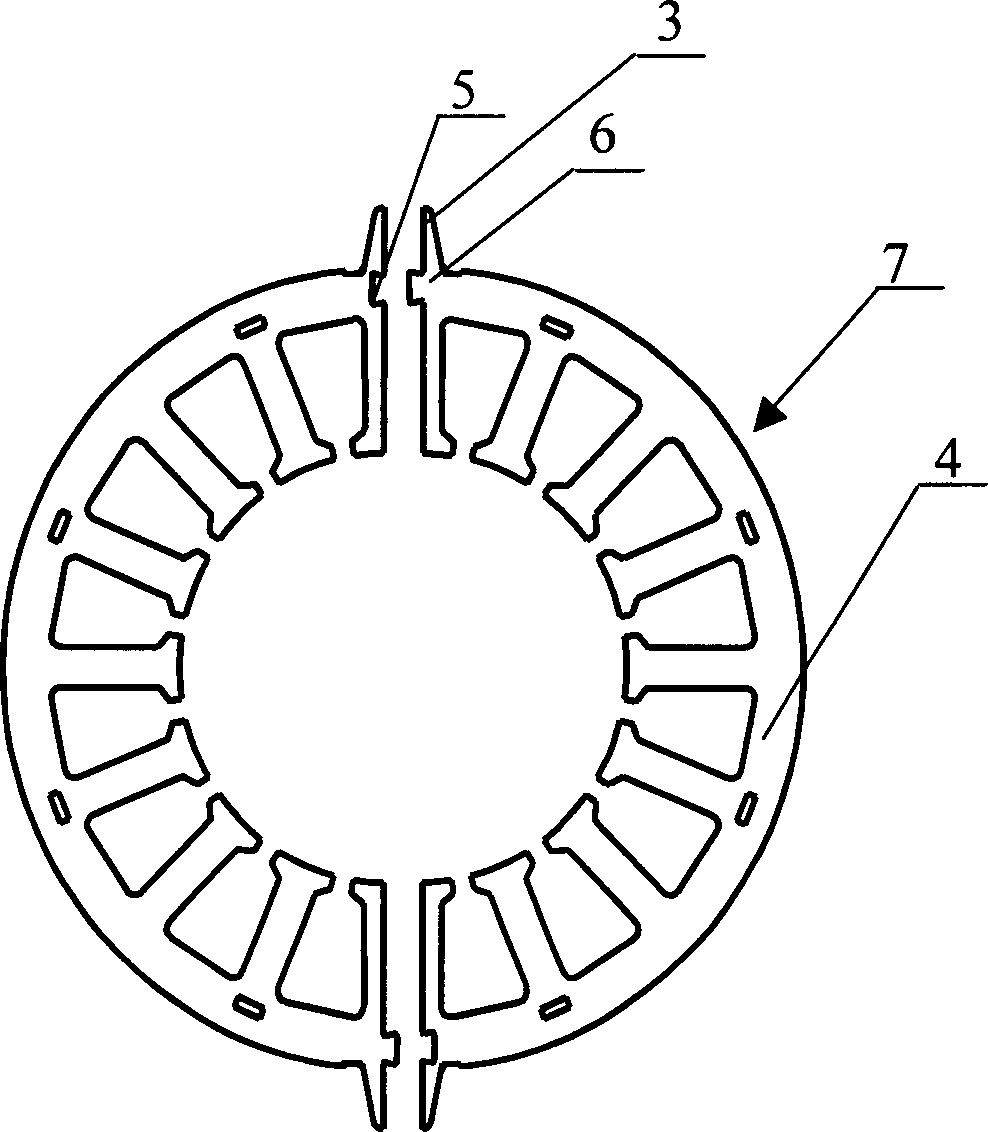
[0021] Such as figure 2 As shown, the connection structure of the stator core of the plastic-encapsulated motor includes two mutually symmetrical semicircular core components 4, and on the two ends 3 of the two semicircular core components 4, there are respectively formed corresponding connection structure. After the coils are wound on the two semicircular iron core assemblies 4, the two semicircular iron core assemblies 4 are combined into a circular motor stator 7 through this connection structure.

[0022] The connection structure is that on the two ends 3 of each semicircular iron core assembly 4 , a groove 5 is formed at one end, and a boss 6 that can be embedded in the groove 5 is formed at the other end. After winding the coils on the two semici...


PUM


Abstract

This invention discloses a connection structure of a stator core of a mold-packaged motor including two symmetrical semi-circle core components and the connection structures are formed at both terminals of each component correspondingly, a groove is formed at one end and a convex hump pluggable in the groove on the other end.

Description

technical field [0001] The invention relates to a plastic-encapsulated motor stator. In particular, it relates to a connection structure of a plastic-encapsulated motor stator core, which has strong concentricity of the motor stator and is easy to assemble. Background technique [0002] The motor consists of a rotor that is press-fitted to a rotating shaft, and a stator that keeps a certain distance from the rotor to rotate the rotor. [0003] The stator includes an iron core and coils. Wherein the stator core includes a plurality of protruding winding portions and slots formed between the winding portions. The coil is wound around the winding portion of the iron core. The shape and size of each winding part and groove are consistent. [0004] When power is applied to the coil of the stator, a magnetic flux will be formed in the gap between the stator and the rotor, and the distribution of the magnetic flux in the gap must be in the form of a sine wave, which is benefici...

Claims


Application Information

Patent Timeline
Patent Type & Authority Applications(China)
IPC IPC(8): H02K1/12
Inventor 王赫
Owner LG ELECTRONICS (TIANJIN) APPLIANCES CO LTD
Why Eureka
Try Eureka