Rolling method for overcoming compound wave shape

A composite wave and plate shape technology, applied in contour control and other directions, can solve problems such as long response time and slow heat transfer speed

Active Publication Date: 2006-06-14
BAOSHAN IRON & STEEL CO LTD
View PDF0 Cites 34 Cited by
  • Summary
  • Abstract
  • Description
  • Claims
  • Application Information

AI Technical Summary

Problems solved by technology

However, due to the long response time caused by the slow heat transfer speed and the limitation of heat conduction caused by the local deviation of the roll temperature, the effect of this method to eliminate high-order waves is very limited.
However, in the actual production situation, many problems encountered are often attributed to the ability to control the M-type and W-type high-order waves, so the control of high-order waves is a very important process factor

Method used

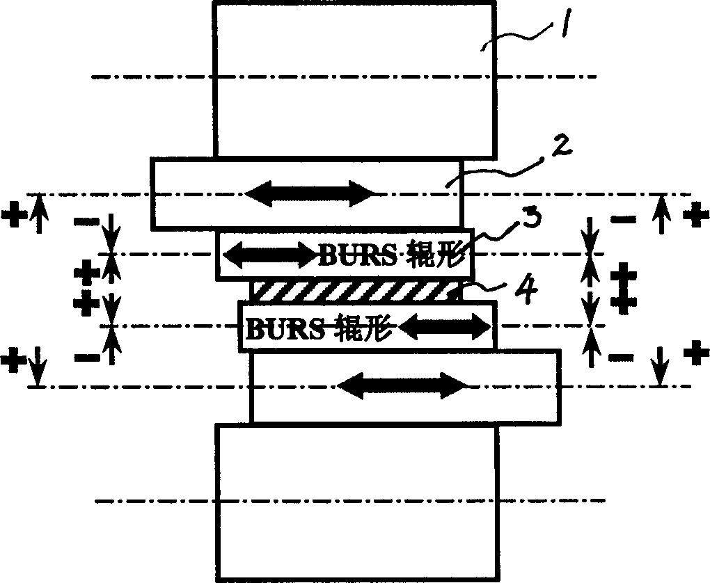
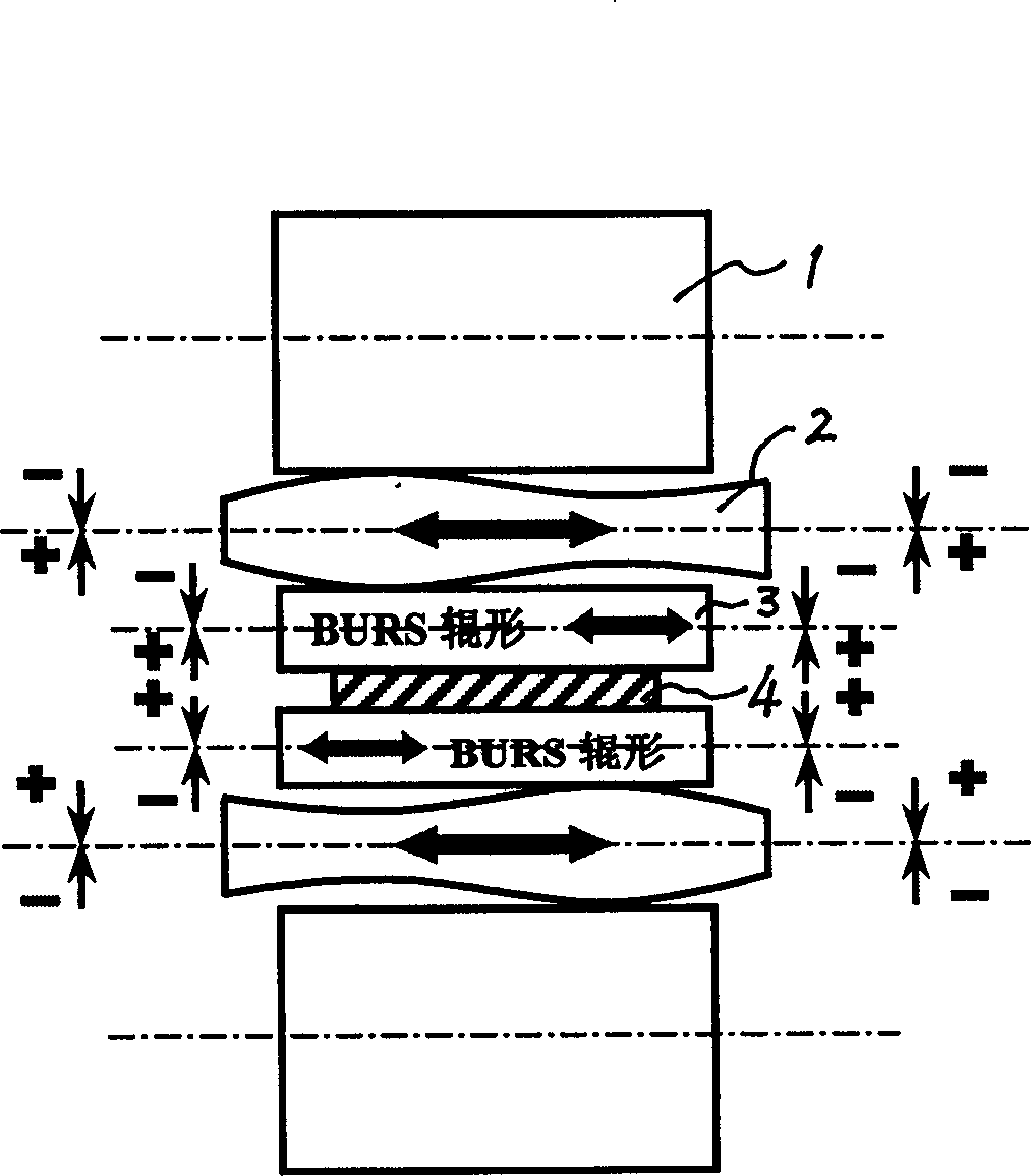
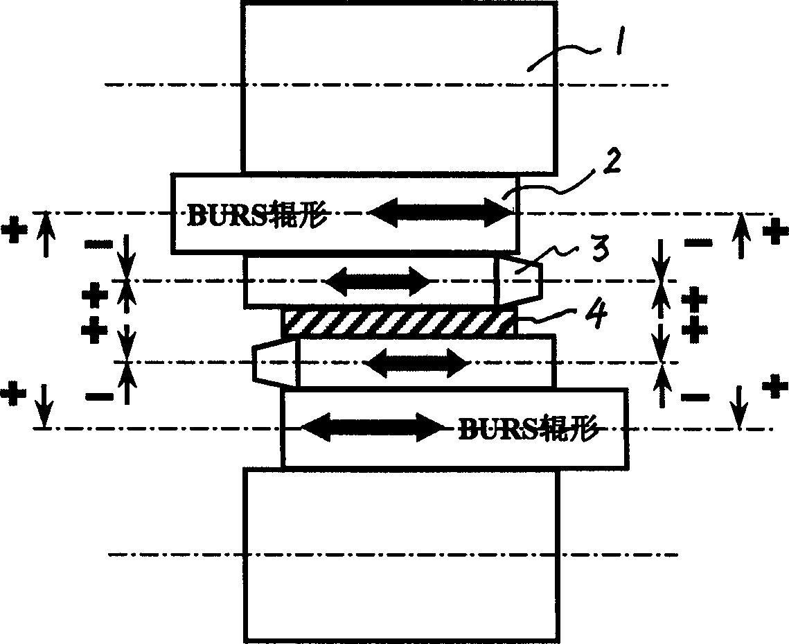

Image

  • Rolling method for overcoming compound wave shape
  • Rolling method for overcoming compound wave shape
  • Rolling method for overcoming compound wave shape

Examples


Embodiment

[0120] Assume that for a 4-high rolling mill, the diameter of the work roll is 500mm, the length of the roll surface is 2000mm, and the width of the strip steel is 1800mm-1000mm, high-order defects are prone to occur at the symmetrical 1 / 4 position on both sides, see Figure 5 :

[0121] For this purpose, the design roll gap is as follows:

[0122] Secondary convexity of the whole roll surface: 200μm;

[0123] High order convexity: 30μm;

[0124] Determine the roll shape according to the shape of the roll gap as follows:

[0125] y=c 0 +c 1 ·x+c 2 x 2 +c 3 x 3 +c 4 x 4 +c 5 x 5 +c 6 x 6 +c 7 x 7 +c 8 x 8 +c 9 x 9

[0126] c 0 =500

[0127] c 1 =0.00027586887550113

[0128] c 2 =8.799468063602584×10 -8

[0129] c 3 =-4.704429994380516×10 -9

[0130] c 4 =2.2971381877533835×10 -11

[0131] c 5 =-4.525431832112869×10 -14

[0132] c 6 =4.499916884881123×10 -17

[0133] c 7 =-2.404927260411608×10 -20

[0134] c 8 =6.607807466785785×10 -2...


PUM


Abstract

A rolling method for overcoming the complex wave shape features that a rolling mill which has special pass configuration and contains at least 4 rollers (supporting roller and working rollers or intermediate rollers) and a plate shape control system are used. The plate shape controlling steps includes measuring plate shape data, processing to obtain plate shape signal, calculating plate shape deviation, and finding out the control signal of plate shape controller by polynomial fitting method or influence function method.

Description

(1) Technical field [0001] The invention relates to metallurgical production technology, in particular to a rolling method for overcoming compound waves. (2) Background technology [0002] During the rolling of flat products, the metal is plastically deformed by the interaction between the roll pair and the metal being processed to achieve the desired shape. For various reasons, the surface of the rolled strip is not a flat surface, but undulating. This undulation, also known as flatness, has a direct correspondence with the change in crown of the strip before and after rolling. The so-called convexity refers to the thickness difference or thickness difference distribution of the cross-section of the strip steel. In this specification, unless otherwise specified, the convexity generally refers to the thickness difference distribution of the cross-section of the strip steel, and the high point or low point on the cross-section The position of the point is called the convexi...

Claims


Application Information

Patent Timeline
Patent Type & Authority Applications(China)
IPC IPC(8): B21B37/28
Inventor 李山青许健勇周坚刚吴平冯莲芹陈军熊斐姜正连王康健朱简如
Owner BAOSHAN IRON & STEEL CO LTD
Why Eureka
Try Eureka