Method and device for moving heavy object

A technology for heavy objects and moving rails, applied in the direction of hoisting device, lifting device, etc., can solve the problems of large uncertainty, concentration on one or several wheels, deformation of the base surface, etc., to achieve the effect of convenient control

Inactive Publication Date: 2006-06-14
中船海洋与防务装备股份有限公司
View PDF0 Cites 4 Cited by
  • Summary
  • Abstract
  • Description
  • Claims
  • Application Information

AI Technical Summary

Problems solved by technology

In this method, the control of the moving speed and moving distance of the heavy object is completely dependent on the operator, and the uncertainty is large. In addition, the inertia of the heavy object is large. During the moving process, there is a possibility of overturning due to excessive changes in the moving speed
In addition, when heavy objects are placed on the trolley, when the moving base surface is uneven or the wheel heights of the wheeled vehicles are inconsistent, the pressure of the heavy objects on the base surface may be concentrated on one or several wheels, causing the base surface to deform during the movement of the heavy objects. or damaged

Method used


Image

  • Method and device for moving heavy object
  • Method and device for moving heavy object
  • Method and device for moving heavy object

Examples


Embodiment 1

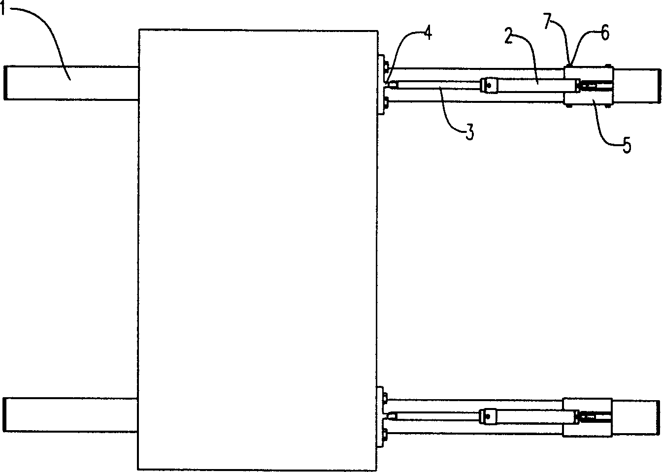
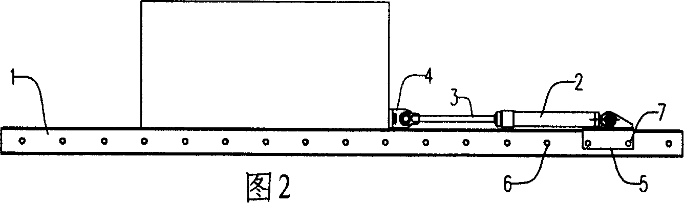
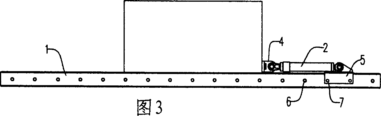
[0016] Example 1, such as figure 1 As shown, a device for moving heavy objects according to the present invention includes: a moving track 1 and a hydraulic cylinder 2 laid on the moving foundation surface, and a connecting piece 4 for connecting heavy objects is provided at the end of the piston rod 3 of the hydraulic cylinder 2 , the base 5 of the hydraulic cylinder 2 is in a "U" shape with the opening downward, the base 5 is stuck on the track 1, and can slide along it, the side of the track 1 and the base 5 are provided with screw holes 6, and the fastener bolts 7 can be screwed in to secure it.

[0017] When moving heavy objects, first pave the moving track 1, place the heavy objects on the moving track 1, pull out the piston rod 3 and connect the heavy objects with the connecting piece 4, and move the "U"-shaped base 5 to the appropriate position along the track 1. position, screw the bolt 7 into the screw hole 6 on the side of the rail 1 and the base 5, fasten the hydr...

Embodiment 2

[0020] Example 2, such as Figure 4 As shown, another device for moving heavy objects according to the present invention includes: a moving track 1 and a hydraulic cylinder 2 laid on the moving base surface, and the end of the piston rod 3 of the hydraulic cylinder 2 has a connecting piece for connecting the heavy objects 4. There is a long groove 8 on the moving track, the base 5 of the hydraulic cylinder 2 is an insert 9, the insert 9 is inserted into the long groove 8, there is a through hole 10 running through the track, and the insert also has a through hole 10, A fastener pin 11 can be inserted to fasten it.

[0021] In order to save costs and shorten the length of the moving track, in this embodiment, the moving track 1 can be formed by connecting multiple segments 12 .

[0022] In order to strengthen the strength of the moving track 1, reinforcing rods 13 can be added between the tracks.


PUM


Abstract

The present invention relates to a method for moving weight and its equipment. Said method includes the following steps: firstly, laying moving trackway on the moving foundation surface, placing the weight on the moving trackway, then using hydraulic cylinder to pull weight sectionally and make the weight be forward moved along the trackway. Said equipment includes the components of hydraulic cylinder, piston rod, connecting piece and fastening piece, etc.

Description

technical field [0001] The invention relates to a method and a device for moving a heavy object, in particular to a method and a device for moving a large heavy object. technical background [0002] Due to their size and weight, large heavy objects usually require winches to move them. When moving, the heavy object is placed on the cart, one end of the cable is tied to the heavy object and the cart, and the other end is wound on the reel of the winch, and the heavy object is pulled by winding the cable through the reel. In this method, the control of the moving speed and moving distance of the heavy object is completely dependent on the operator, and the uncertainty is large. In addition, the inertia of the heavy object is large. During the moving process, there is a possibility of overturning due to excessive changes in the moving speed . In addition, when heavy objects are placed on the trolley, when the moving base surface is uneven or the wheel heights of the wheeled c...

Claims


Application Information

Patent Timeline
Patent Type & Authority Applications(China)
IPC IPC(8): B66F19/00
Inventor 段昌辉
Owner 中船海洋与防务装备股份有限公司
Why Eureka
Try Eureka