Detector for detecting when the thread bobbin in a thread-processing system has to be replaced

A technology for processing systems and monitors, applied in the field of monitors, can solve problems such as pollution of photoelectric monitors, and achieve the effect of eliminating the danger of yarn damage

Active Publication Date: 2010-05-05
IROPA AG (CH)
View PDF3 Cites 0 Cited by
  • Summary
  • Abstract
  • Description
  • Claims
  • Application Information

AI Technical Summary

Problems solved by technology

The photoelectric monitor is operationally safe against unavoidable contamination and must be calibrated individually for different yarn qualities and / or yarn thicknesses

Method used


Image

  • Detector for detecting when the thread bobbin in a thread-processing system has to be replaced
  • Detector for detecting when the thread bobbin in a thread-processing system has to be replaced
  • Detector for detecting when the thread bobbin in a thread-processing system has to be replaced

Examples


Embodiment Construction

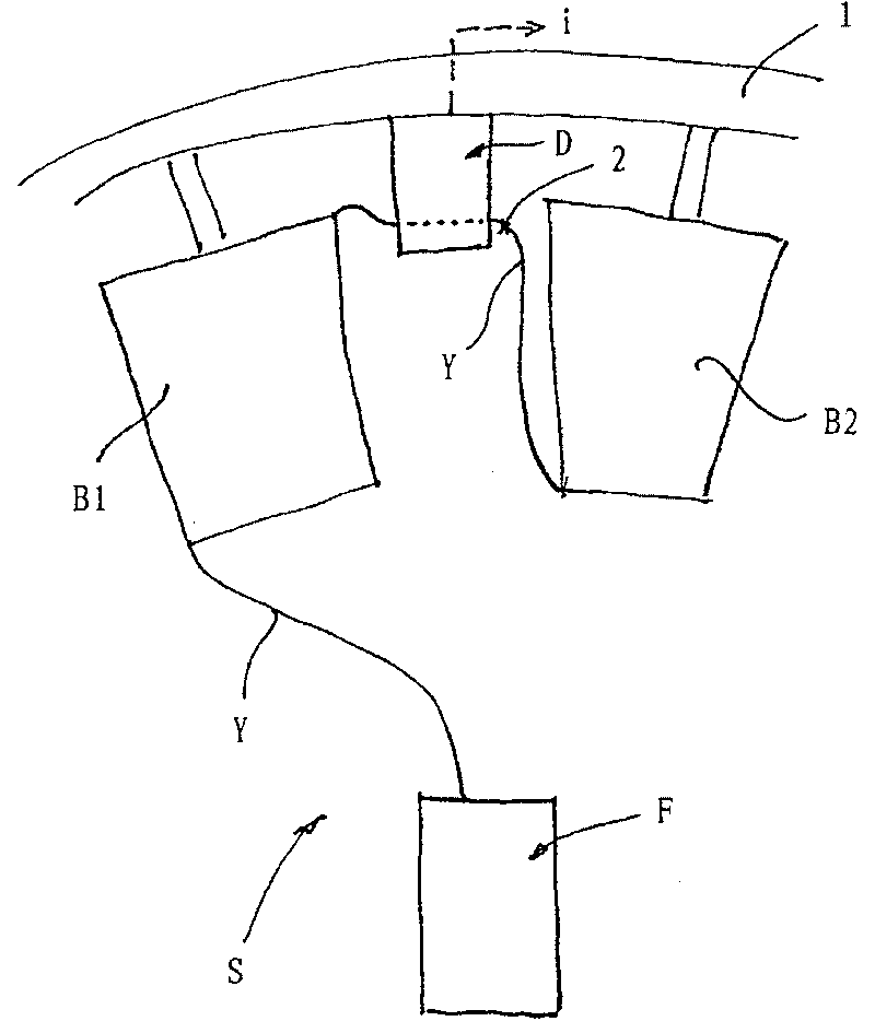
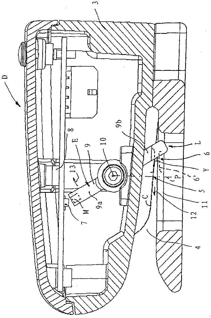
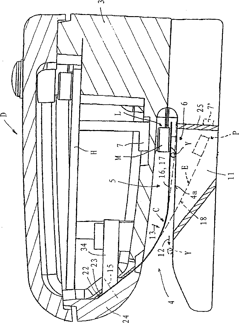
[0029] Such as figure 1, in a yarn processing system S, two bobbins B1, B2 carrying the same yarn Y are mounted on creel 1, for example. A yarn processing device F, such as a yarn feeding device, draws yarn Y from said respective yarn bobbins B1, B2. The end of the yarn Y on one yarn bobbin B1 is connected by a knot to the front end of the yarn Y on the other yarn bobbin B2 (pigtail). For example, on the creel 1, a monitor D is installed at the position where the connection portion of the yarn Y is located.

[0030] When the yarn Y is exhausted from the yarn spool B1, the second yarn spool B2 produces a yarn spool change. During the changeover, the connection is pulled out of the monitor D before the yarn Y is thereafter withdrawn from the second yarn spool B2. During this transformation, the monitor D generates a signal i indicative of the transformation that has taken place. In some cases, the monitor D is designed such that during loading of the yarn Y to the monitor D,...


PUM


Abstract

The invention relates to a detector (D) for detecting when the thread bobbin in a thread-processing system (S) has to be replaced. Said detector comprises a movably received element (E), at least onedetection member (7) that responds to a relative position or a relative position change of the element with a signal (i), and a power generator that exerts a force on the element, and the element (E)can be adjusted during the replacement. The force is oriented in the direction of movement of the element (E) towards the detection position (P). The positioning device is provided with a thread clamping area (6, 6') that is arranged relative to the path of travel of the element in such a manner that the positioned thread (Y), until the replacement, forms a barrier for the element (E) against a movement towards the detection position (P) in response to the exerted force. The thread, during replacement, becomes detached in such a manner that the element (E) automatically moves towards the detection position (P).

Description

technical field [0001] The invention relates to a monitor for monitoring yarn spool changes in a yarn processing system, said monitor being provided with a movable support element which can be moved between a loading position and a movement between monitoring positions, a yarn positioning device for positioning the yarn within said monitor until the bobbin change occurs, a monitoring element, which responds via a signal within the movement path of the element In response to a relative position of the element or a change in the relative position, and a pressure generator, the pressure generator exerts pressure on the element in the direction of movement of the element. Background technique [0002] The monitor described in patent EP 0454199A has an asymmetric, pivotable, angled support rod with two arms. Due to the asymmetrical design, a pressure generator is integrated in the rod for generating the pressure which brings an arm of which an element is formed into the loaded p...

Claims


Application Information

Patent Timeline
Patent Type & Authority Patents(China)
IPC IPC(8): D03D49/00B65H63/00D03D47/34B65H49/12B65H63/08
CPCB65H49/12D03D47/34B65H63/086B65H2701/31
Inventor 拉斯·黑尔格·戈特弗里德·涛兰德比约恩·哈尔瓦松亨里克·斯文松
Owner IROPA AG (CH)
Why Eureka
Try Eureka