A padlock

A padlock and lock shell technology, applied in padlocks, combination locks, building locks, etc., can solve problems such as large lock shells, and achieve the effect of simple design and strong reminder effect.

Inactive Publication Date: 2010-06-09
尤俊德
View PDF9 Cites 0 Cited by
  • Summary
  • Abstract
  • Description
  • Claims
  • Application Information

AI Technical Summary

Problems solved by technology

The problem with this padlock is that its housing must be made larger in order to retract into the shackle sleeve
In addition, the padlock does not have any indicator to indicate whether it has been opened with a key

Method used


Image

  • A padlock
  • A padlock
  • A padlock

Examples


Embodiment Construction

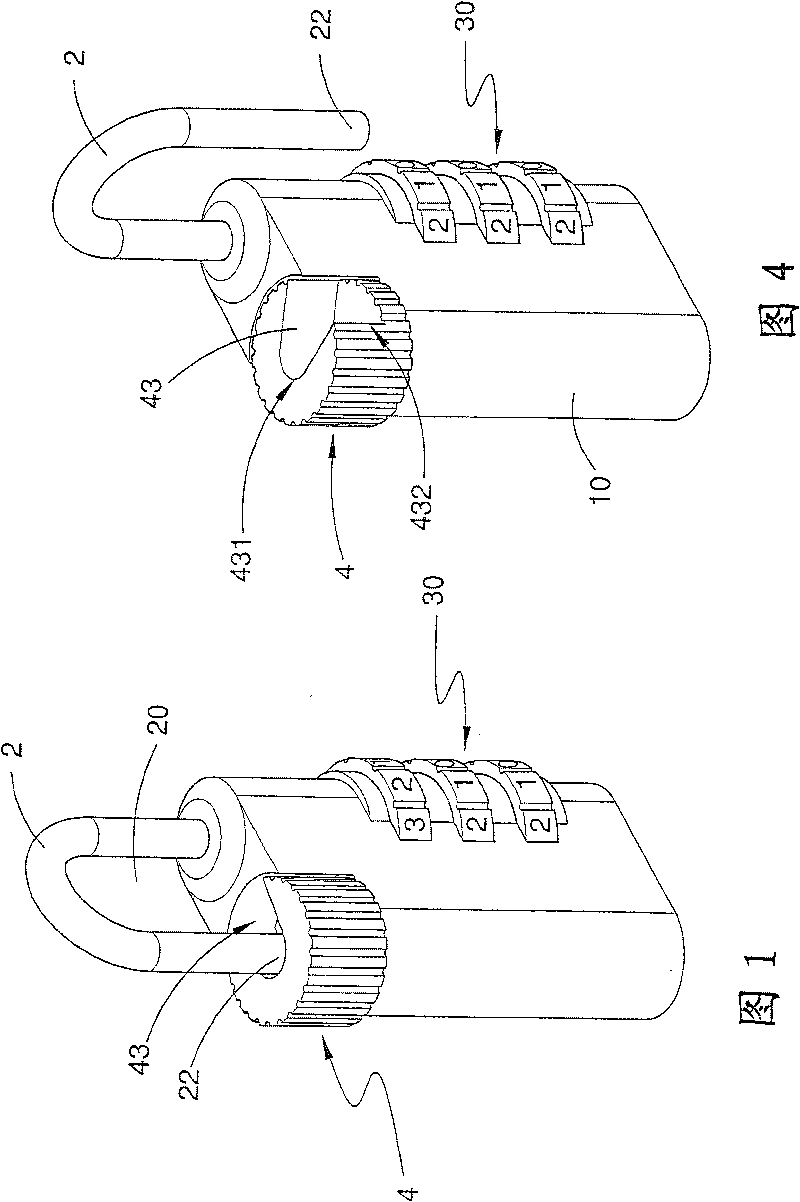
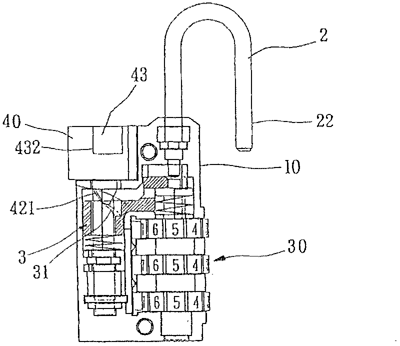
[0071] exist Figures 1 to 4 The padlock shown in is the first preferred embodiment of the invention. exist figure 1 It is pointed out that the padlock has a stopper 4 and a lock hook 2, and the lock hook 2 extends to the stopper 4 for enclosing an area 20, and the stopper 4 and the lock hook 2 are all arranged to be movable, so as to To enable one to leave the other. The padlocks disclosed in the subsequent examples all have this feature despite their different shapes. It should be noted that all the examples include a device corresponding to the stopper 4, and the present invention does not particularly focus on some related designs of the device.

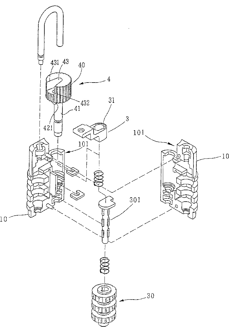
[0072] see figure 1 , 2 , the stopper 4 includes a limiting button 40 and a base 41, the limiting button 40 has a receiving groove 43, and the receiving groove 43 has a first opening 431 and a second opening 432, the two are located respectively On the top surface and the side surface of the limiting button 40 . The lock h...


PUM


Abstract

A padlock includes a stop dog, a shackle and an indication element. The stop dog includes a restriction portion, the shackle extends into the restriction portion, the indication element mounts to therestriction portion movably. Wherein, the restriction portion is set to be moveable, cause to it can be separated a distance from the shackle, the indication element is set to be changed from a firstposition to a second position correspondingly according to the movement of the restriction portion, and only when the padlock is adjusted to an authorized code, the indication element can be return tothe first position from the second position.

Description

technical field [0001] The invention relates to a padlock, which is different from ordinary padlocks in that the padlock has a stopper and a lock hook, the stopper has a limit button, the lock hook extends to the limit button, and the limit button is arranged as It can be determined whether to stagger a certain distance from the lock hook by changing the position. Background technique [0002] Most padlocks only achieve the purpose of locking the locked object through a shackle and a lock case. Patents such as US1,597,560, US4,751,830 and US6,539,761 are typical examples of such padlocks. [0003] In the US6,877,345 patent case, another padlock is disclosed. Although this padlock also has a shackle and a lock case, an indicator is additionally assembled in the lock case, and a window hole is formed on the lock case. for viewing the indicator. The indicator will normally display a first color in the window, but when the padlock is opened by a key, the indicator will displa...

Claims


Application Information

Patent Timeline
Patent Type & Authority Patents(China)
IPC IPC(8): E05B67/10E05B67/12E05B37/02E05B37/22E05B17/22
Inventor 尤俊德
Owner 尤俊德
Why Eureka
Try Eureka