Supercharge Your Innovation With Domain-Expert AI Agents!

Lock structure

A technology of structure and snap-fit ​​holes, which is applied to quick-action fasteners, electrical components, flip/rocker switches, etc., can solve problems such as poor contact of the switch mechanism, and achieve the effect of preventing flying

Active Publication Date: 2006-06-21
KK TOKAI RIKA DENKI SEISAKUSHO
View PDF0 Cites 2 Cited by
  • Summary
  • Abstract
  • Description
  • Claims
  • Application Information

AI Technical Summary

Problems solved by technology

Then, the fitting burr 8 falls on the workbench, adheres to other components, and enters the inside of the switch mechanism of the switch device. This is the cause of poor contact of the switch mechanism.

Method used


Image

  • Lock structure
  • Lock structure
  • Lock structure

Examples


Embodiment Construction

[0020] Below, refer to Figure 1 to Figure 6 An example of the present invention will be described.

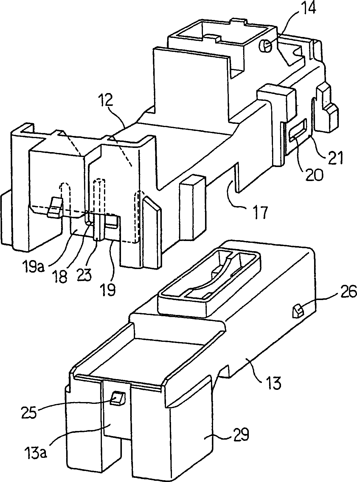
[0021] First, in Figure 4 as well as Figure 5 In Fig. 1 , a switch device 11 for a window regulator in automatic opening and closing of windows of an automobile is shown. This switch device 11 is made up of following parts: switch main body 12, the insulator 13 that is assembled in the bottom of this switch main body 12, the operation button 15 that is installed on the top of switch main body 12 and can shake by shaft 14, is arranged in switch main body 12 inside The switch mechanism 16 (refer to Figure 5 ).

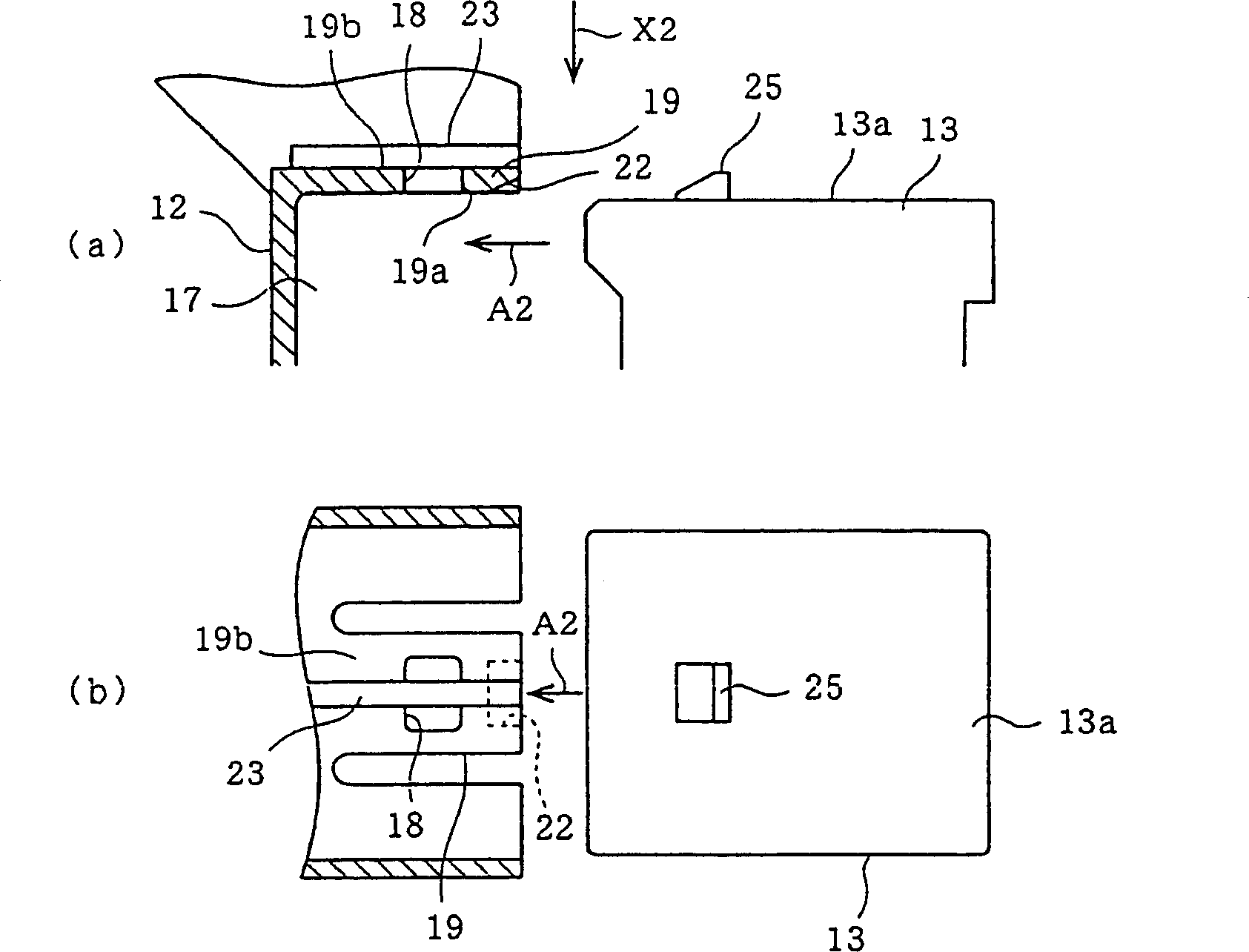
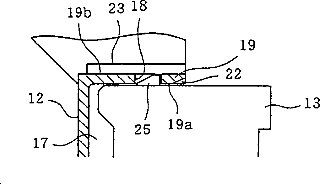
[0022] Among them, the switch main body 12 is formed of synthetic resin such as ABS resin, and at its lower part, such as image 3 As shown in FIG. 2 , a receiving portion 17 of a rectangular frame body with an open bottom side is formed. At the front of the peripheral wall portion of the receiving portion 17 ( image 3 as well as Figure 5 The left side in th...


PUM


Abstract

An engaging structure, on the outer surface (19b) of a first engaging piece (19) having a first engaging hole (18), a bridging portion ( twenty three). When the first engaging protrusion (25) of the insulator (13) is engaged in the engaging hole (18) of the switch main body (12), because the engaging protrusion (25) and the engaging piece (19) are Interference, so the engaging convex portion (25) cuts the inner surface (19a) of the engaging piece (19), and a so-called fitting burr occurs. Even if a fitting burr occurs, the fitting burr is prevented from being scattered from the engaging hole (18) to the outside by colliding with the bridging portion (23) provided across the engaging hole (18).

Description

technical field [0001] The present invention relates to an engaging structure in which an engaging hole and an engaging protrusion are engaged with each other by a so-called snap fit structure. Background technique [0002] Conventionally, for example, in a switchgear, when a switch main body and an insulator provided with a fixed contact are assembled together, a so-called slide-fit structure is used to engage them. [0003] exist Figure 7 as well as Figure 8 In , an example of its engaging structure is shown. Figure 7 It shows the state before the switch main body and the insulator are assembled, (a) shows a partially cutaway side sectional view, (b) shows a view from the arrow X1 direction of (a); and, Figure 8 A side sectional view showing the assembled state of the switch body and the insulator. [0004] exist Figure 7 Among them, the switch main body 1 is formed of synthetic resin such as ABS resin, and has a housing portion 2 . Around the accommodating portion...

Claims


Application Information

Patent Timeline
Patent Type & Authority Applications(China)
IPC IPC(8): F16B21/06H01H23/00
Inventor 白井信司
Owner KK TOKAI RIKA DENKI SEISAKUSHO
Features
  • R&D
  • Intellectual Property
  • Life Sciences
  • Materials
  • Tech Scout
  • Unparalleled Data Quality
  • Higher Quality Content
  • 60% Fewer Hallucinations
Learn More