
Metering display with automatic temperature difference compensation for oil filling machine

A technology of temperature difference compensation and display, applied in the electrical field, can solve problems such as inaccurate measurement and achieve the effect of protecting fairness

Inactive Publication Date: 2006-06-21
SHANGHAI ZHONGYOU ENTERPRISE GRP CO LTD
View PDF0 Cites 0 Cited by
  • Summary
  • Abstract
  • Description
  • Claims
  • Application Information

AI Technical Summary

Problems solved by technology

Because the flowmeter measures the volume of fuel, and the volume of fuel will change according to the change of temperature, making the measurement inaccurate

Method used


Image

  • Metering display with automatic temperature difference compensation for oil filling machine

Examples


Embodiment Construction

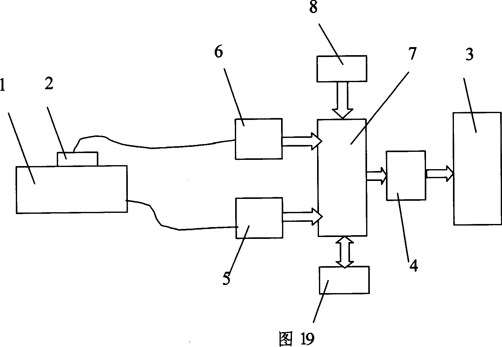
[0011] As shown in Figure 1, the fuel dispenser metering display of automatic temperature difference compensation of the present invention is made of flowmeter 1, temperature sensor 2 and electronic counter, and described flowmeter 1 is provided with flow signal output interface, and in described electronic counter A flow signal input interface is provided, a display 3, a display drive circuit 4 and a power supply circuit are provided in the electronic counter, and the display 2 is connected to the display drive circuit 4, wherein the electronic counter is provided with There is a first analog-to-digital conversion circuit 5 and a second analog-to-digital conversion circuit 6, the first analog-to-digital conversion circuit 1 is connected to the flow signal input interface, and the second analog-to-digital conversion circuit 6 Connected with the temperature sensor 2, the temperature sensor 2 is fixedly attached to the flow meter 1, the first analog-to-digital conversion circuit ...


PUM


Abstract

The invention discloses a fuel charger measuring display of self-thermocompensation, which comprises the following parts: flowmeter, thermal sensor and electronic counter, wherein the flow signal output interface is set on the flowmeter; the electronic counter contains display, driving display circuit and power; the first and second module transmission circuit is set in the electronic counter; the first module transmission circuit connects the flow signal input interface; the second module transmission circuit connects the temperature sensor, which is attached on the flowmeter; the microprocessor amends the real-time flow signal according to the temperature variation in connection with the first and second module transmission circuit, which keeps the accurate precision of fuel charger and fair fuel business against the influence of temperature.

Description

Technical field: [0001] The invention relates to the electrical field, in particular to an electronic gauge for a fuel dispenser, in particular to a fuel dispenser metering display with automatic temperature difference compensation. Background technique: [0002] In the prior art, fuel dispensers widely used in commercial gas stations are mainly composed of explosion-proof motors, oil pumps, oil-gas separators, flow meters, electronic counters and oil guns. Its working process is: when taking off the refueling gun, the electronic counter starts the motor and the electromagnetic valve after receiving the starting signal of the gun. The motor drives the oil pump to suck the fuel from the oil tank through the oil delivery pipe, bellows and filter. The oil pump pressurizes the fuel and then enters the oil-air separator. The oil-air separator separates the gas in the fuel and discharges it out of the machine. The final fuel pushes the four pistons to reciprocate, and drives the ...

Claims


Application Information

Patent Timeline
Patent Type & Authority Applications(China)
IPC IPC(8): G01F15/02G01F15/06G01F15/07
Inventor 蒋妙范
Owner SHANGHAI ZHONGYOU ENTERPRISE GRP CO LTD
Learn More