Liquid crystal display device with optical compensation

A liquid crystal display device and a technology for optical compensation, which are applied in the directions of optics, nonlinear optics, static indicators, etc., can solve the oblique light leakage of orthogonal polarizers, reduce the contrast and viewing angle, and reduce the contrast of a light compensation bending mode liquid crystal display device. perspective, etc.

Inactive Publication Date: 2006-06-21
CHUNGHWA PICTURE TUBES LTD
View PDF0 Cites 6 Cited by
  • Summary
  • Abstract
  • Description
  • Claims
  • Application Information

AI Technical Summary

Problems solved by technology

[0004] Please refer to Figure 1B , Figure 1B Shown is a full viewing angle diagram of a known optically compensated bending mode liquid crystal display device. The isocontrast line 19 in the figure represents a viewing angle area with a contrast ratio of 10:1. Although the above-mentioned optically compensated bending mode liquid crystal display device has the characteristics of quick response, its The central contrast is only about 30:1 to 40:1. The reason for this is that when the light-compensated bending mode liquid crystal display device is driven to the dark state voltage, dark state light leakage occurs due to the optical anisotropy of liquid crystal molecules. , In addition, the two crossed polarizers will also produce oblique light leakage, which will reduce the contrast and viewing angle
[0005] As mentioned above, both the dark-state light leakage of the liquid crystal layer and the oblique light leakage of the two crossed polarizers will reduce the contrast and viewing angle of a light-compensated bending mode liquid crystal display device, so the above-mentioned light leakage phenomenon must be overcome

Method used


Image

  • Liquid crystal display device with optical compensation
  • Liquid crystal display device with optical compensation
  • Liquid crystal display device with optical compensation

Examples


Embodiment Construction

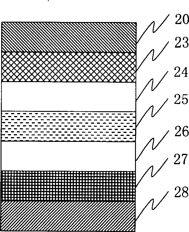
[0049] Please refer to Figure 2A , Figure 2AShown is the optically compensated bending mode liquid crystal display device with a phase compensation plate of the present invention, which includes a first substrate 24, a second substrate 26, a liquid crystal layer 25, a first phase compensation plate 23, a second phase compensation plate 27, a first polarizer 20 and a second polarizer 28, wherein the second substrate 26 is arranged parallel to the first substrate 24, and the liquid crystal layer 25 is arranged between the first substrate 24 and the second substrate 26 , the liquid crystal alignment mode of the liquid crystal layer 25 is optical compensation bending mode, the first phase compensation plate 23 is arranged outside the first substrate 24, the second phase compensation plate 27 is arranged outside the second substrate 26, and the first phase compensation plate 27 is arranged outside the second substrate 26. The phase compensation plate 23 and the second phase comp...


PUM


Abstract

The invention discloses a LCD of optical compensation, which comprises the following parts: first base plate, second base plate, liquid crystal layer, the first-phase compensating plate, second-phase compensation plate, optical compensation film, first polarizing plate and second polarizing plate, wherein the liquid crystal array pattern of liquid crystal layer displays optical compensation bent pattern; the first-phase compensating plate is set on the exterior of the first base plate; the second-phase compensation plate is set on the exterior of second base plate; multilayer non-cylinder liquid crystal is contained in the first-phase compensation plate and second-phase compensation plate, which reduces the dark mesh-light of liquid crystal layer; the optical compensation film adapts the single-axle extension delaying-piece on the exterior of the first-phase compensation plate, which reduces the incidence mesh-light of two pieces of orthogonal polarizing plate. The invention improves the LCD comparison and aspect angle effectively.

Description

technical field [0001] The present invention relates to a liquid crystal display device with optical compensation, in particular to a liquid crystal display device with an optical compensation bend (Optical Compensated Bend) mode. Background technique [0002] After rapid development in recent years, liquid crystal display has significantly improved its various performance indicators, so it gradually replaced the cathode ray tube display used in computers, and further entered the application field of LCD TV. Due to the demand for displaying dynamic images Therefore, the liquid crystal display must have a better response speed to avoid afterimages when displaying dynamic images, and because the picture quality of traditional liquid crystal displays varies greatly from different angles, in order to provide multiple people to watch at the same time, the liquid crystal display It is also necessary to adopt wide viewing angle technology to ensure that the images viewed by each us...

Claims


Application Information

Patent Timeline
Patent Type & Authority Applications(China)
IPC IPC(8): G02B5/30G02F1/133G02F1/1335
Inventor 张圣晖潘建霖
Owner CHUNGHWA PICTURE TUBES LTD
Why Eureka
Try Eureka