Luminescent device

A light-emitting device and light source technology, applied in the direction of lighting devices, independent lighting devices, components of lighting devices, etc., can solve problems such as long scanning time, reduced scanning image quality, and single system voltage of the light-emitting device, so as to increase the ratio, Consistent image quality and reduced scanning time

Inactive Publication Date: 2006-07-05
AVISION PRECISION IND (SUZHOU) CO LTD
View PDF0 Cites 0 Cited by
  • Summary
  • Abstract
  • Description
  • Claims
  • Application Information

AI Technical Summary

Problems solved by technology

[0003] However, since the known lighting device only has a single system voltage V input, it can only provide a fixed brightness of the light source
When the scanner scans the documents to be scanned, such as scanning with a positive film and a negative film, because the light transmittance of the two documents to be scanned is different, if a single light source is used for scanning, the scanning time of one of the documents will be too long. If it is too long or too short, the scanning image quality will be reduced, or when some darker documents to be scanned require a stronger light source brightness, if the system only provides one light source brightness, it will not meet the user's needs for multiple light source brightness

Method used


Image

  • Luminescent device
  • Luminescent device
  • Luminescent device

Examples


Embodiment Construction

[0011] In order to make the above-mentioned purposes, features, and advantages of the present invention more comprehensible, the following specific embodiments, combined with the accompanying drawings, are described in detail as follows:

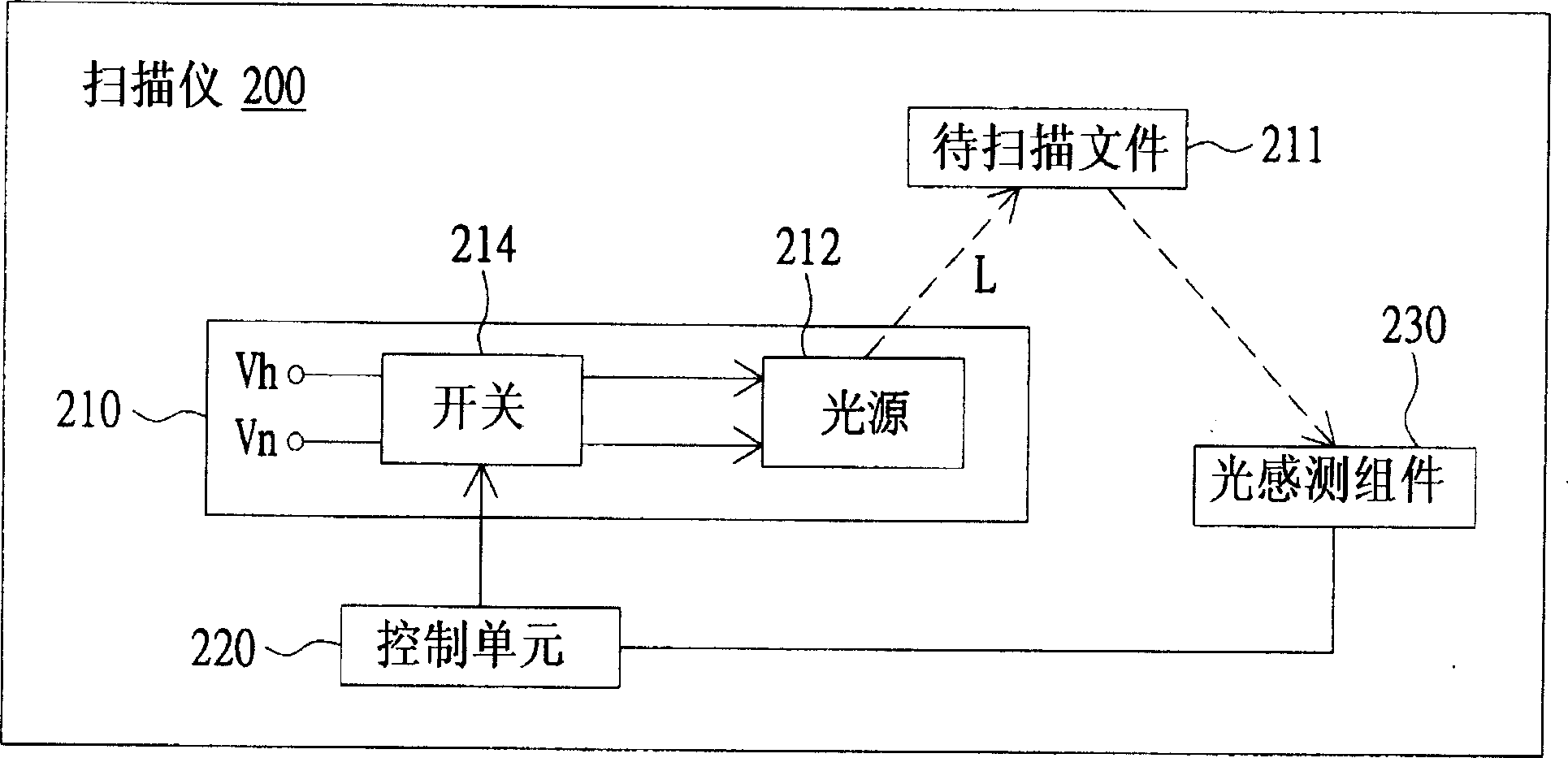
[0012] Such as figure 2 As shown, it shows a schematic structural block diagram of a scanner for reflectively scanning documents to be scanned according to an embodiment of the present invention. The scanner 200 includes a light emitting device 210 , a control unit 220 and a light sensing component 230 . The light emitting device 210 includes a light source 212 and a switch 214 . The light source 212 provides the scanning light L required for sensing the document 211 to be scanned, such as a cold cathode ray tube (CCFL) or a light emitting diode (LED). The switch 214 is used to control the light source 212 to be turned on or off, and provides two different voltages: a high voltage Vh and a normal voltage Vn. The control unit 220 controls...


PUM


Abstract

A luminous device consists of light source and switch. It is featured as providing light for sensing file to be scanned by light source, utilizing switch to selectively input the first voltage or the second voltage to light source for generating the first light source brightness or the second light source brightness correspondingly.

Description

technical field [0001] The invention relates to a light emitting device, in particular to a light emitting device which can provide brightness of more than two light sources. Background technique [0002] figure 1 It is a structural block diagram of a light emitting device in a known scanner. Please refer to figure 1 , the light emitting device 100 includes a light source 110 and a switch 120 . The light source 110 is, for example, a Cold Cathode Fluorescent Lamp (CCFL) or a Light Emitting Diode (LED). The switch 120 is used to control the light source 110 to be turned on and off according to the settings of the user. When the user turns on the switch 120, the system voltage V is input to the light source 110, so that the light source 110 emits light, so as to provide the scanning light source required by the system; When it is turned on, the system voltage V cannot be input to the light source 110, so the light source 110 does not emit light. [0003] However, since t...

Claims


Application Information

Patent Timeline
Patent Type & Authority Applications(China)
IPC IPC(8): F21S6/00F21V23/04H04N1/00
Inventor 林庆源
Owner AVISION PRECISION IND (SUZHOU) CO LTD
Why Eureka
Try Eureka