Adaptive coefficient scan order

A scanning sequence and self-adaptive technology, applied in the direction of digital video signal modification, TV, pulse modulation TV signal transmission, etc., can solve the problem that there is no inherent requirement for the continuity of the scanning mode, etc.

Active Publication Date: 2006-07-05
MICROSOFT TECH LICENSING LLC
View PDF2 Cites 22 Cited by
  • Summary
  • Abstract
  • Description
  • Claims
  • Application Information

AI Technical Summary

Problems solved by technology

While a similar continuous zigzag scan pattern is widely used in JPEG and MPE

Method used


Image

  • Adaptive coefficient scan order
  • Adaptive coefficient scan order
  • Adaptive coefficient scan order

Examples


Embodiment Construction

[0034] The description that follows relates to a digital media compression system or encoder / decoder utilizing adaptive coefficient scan order techniques. For purposes of illustration, one embodiment of a compression system incorporating adaptive coefficient scan order techniques is an image or video compression system. In addition, reversible overlap operators can also be added to compression systems or encoders / decoders for other digital media or 2D data. The adaptive coefficient scan order technique does not require the digital media compression system to encode the compressed digital media in a specific encoding format.

[0035] 1. Encoder / Decoder

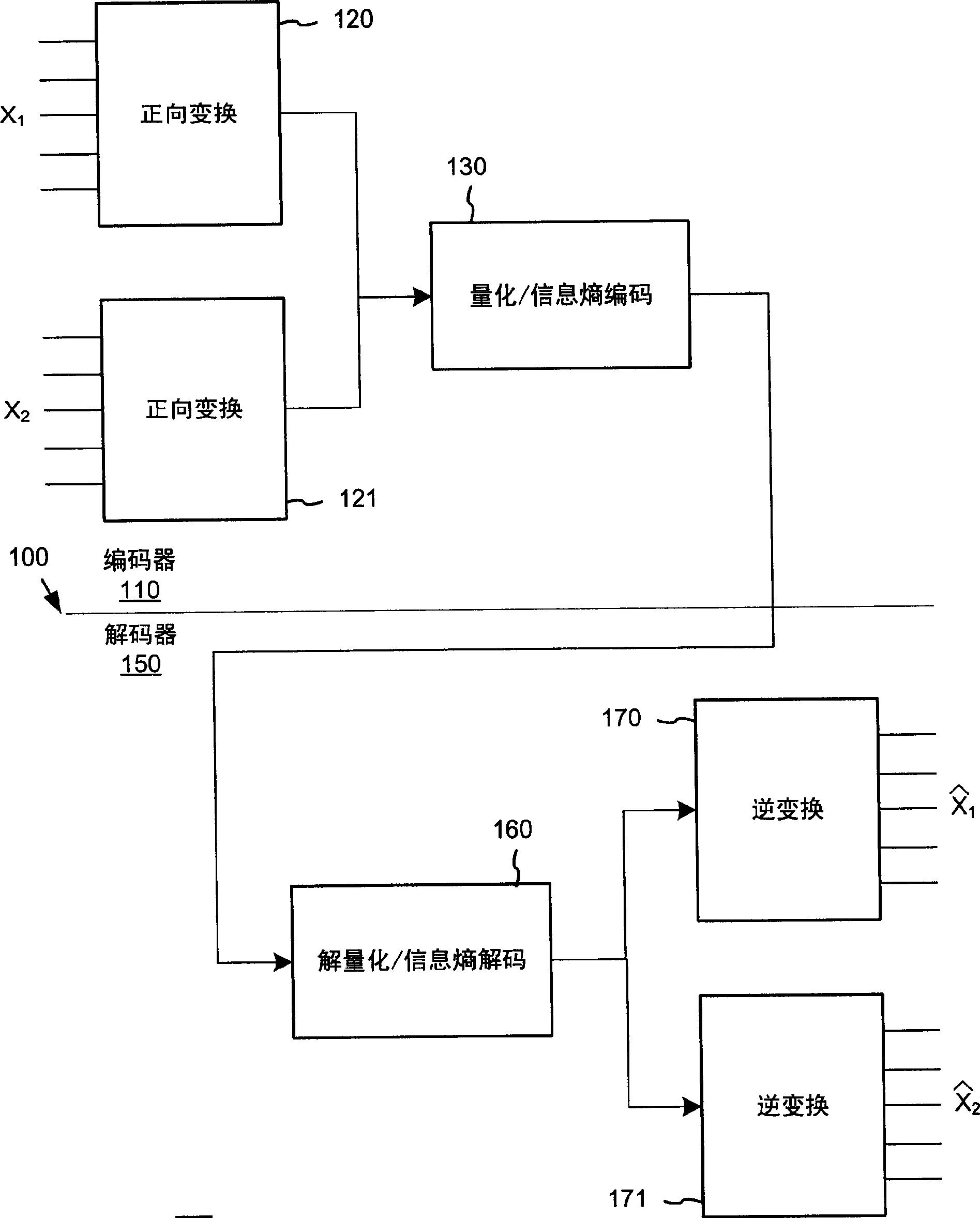
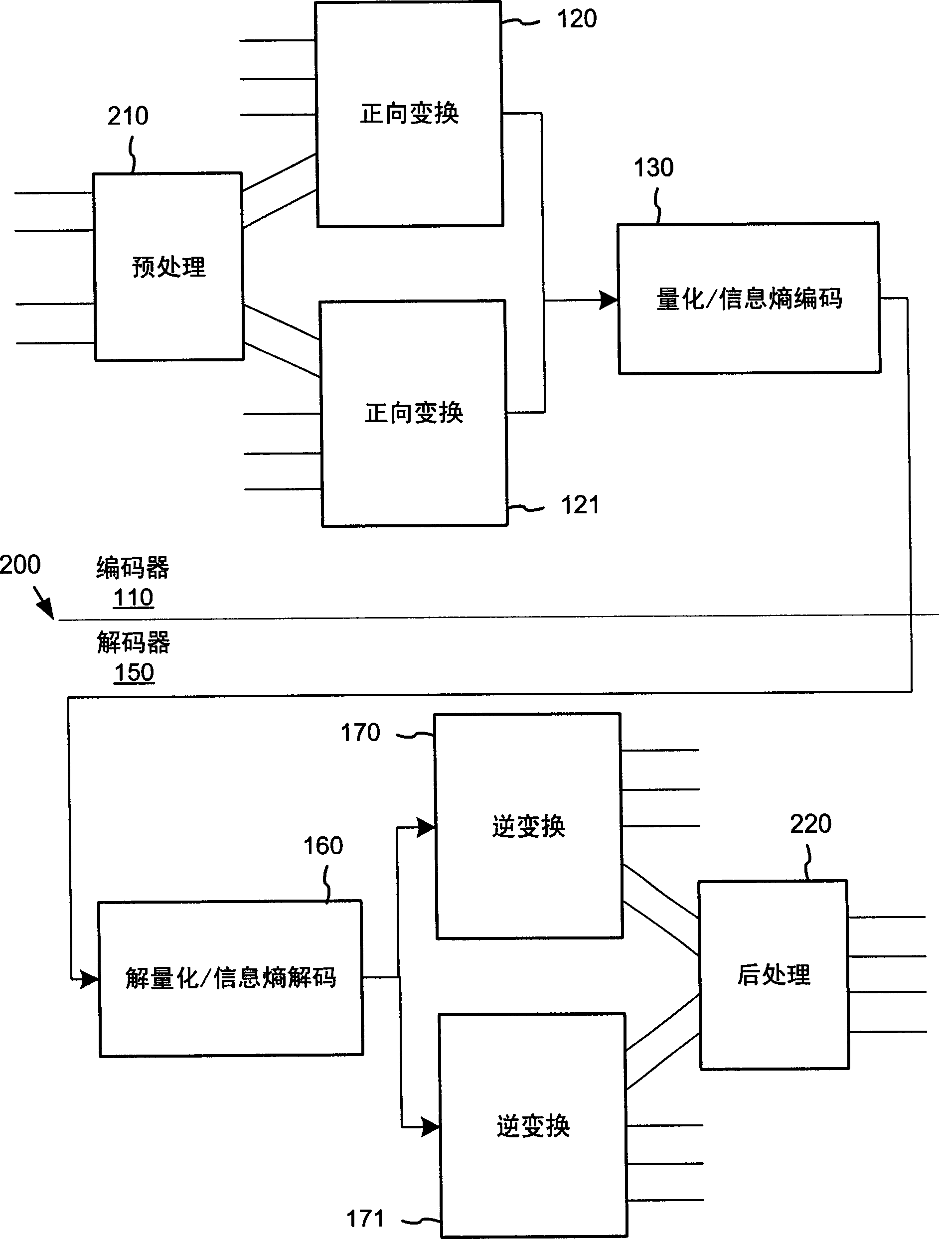
[0036] Figure 4 and Figure 5 is a generalized diagram of the process used in a typical 2-dimensional (2D) data encoder 400 and decoder 500 based on a lapped transform and using adaptive coefficient scan order as will be described more fully below. The schematic diagram represents an inductive or simplified illustration of ...


PUM


Abstract

A digital media codec adaptively re-arranges a coefficient scan order of transform coefficients in accordance with the local statistics of the digital media, so that the coefficients can be encoded more efficiently using entropy encoding. The adaptive scan ordering is applied causally at encoding and decoding to avoid explicitly signaling the scan order to the decoder in the compressed digital media stream. For computational efficiency, the adaptive scan order re-arranges the scan order by applying a conditional exchange operation on adjacently ordered coefficient locations via a single traversal of the scan order per update of the statistical analysis.

Description

technical field [0001] The present invention generally relates to block transform based digital media (eg, video and image) compression. Background technique [0002] An Overview of Block Transform-Based Coding [0003] Transcoding is a compression technique used in many audio, image, and video compression systems. Typically uncompressed digital images and video are depicted or captured as samples of graphic elements or colors at positions within an image or video frame arranged in a two-dimensional (2D) grid. This is called the spatial domain representation of images or videos. For example, a typical format for an image consists of a stream of samples of 24-bit color graphics arranged in a grid. Each sample is a plurality of components representing a color at pixel units in the form of a grid in a color space such as RGB or YIQ. Various imaging and video systems can be sampled using a variety of different color, spatial and temporal resolutions. Similarly, digital audi...

Claims


Application Information

Patent Timeline
IPC IPC(8): H04N7/30H03M7/30H04N1/41H04N19/60
CPCH04N7/30H04N7/26095H04N19/00109H04N19/00775H04N19/00296H04N7/26122H04N19/00139H04N7/2625H04N19/00121H04N19/129H04N19/136H04N19/18H04N19/13H04N19/60
Inventor S·斯里尼瓦杉
Owner MICROSOFT TECH LICENSING LLC
Why Eureka
Try Eureka