Method and apparatus for rope textile treatment
A textile, rope-like technology, applied in the field of rope-like textiles, to achieve the effect of shortening the loading time
- Summary
- Abstract
- Description
- Claims
- Application Information
AI Technical Summary
Problems solved by technology
Method used
Image

Examples
Embodiment 1
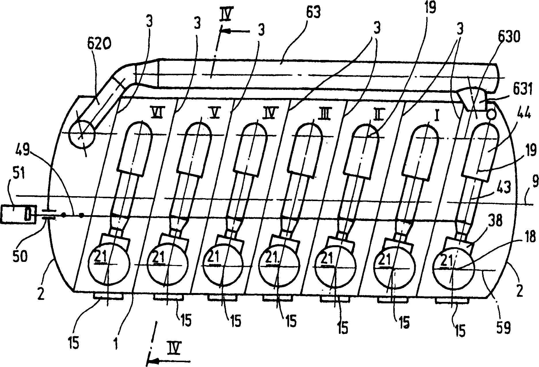
[0049] Alkaline hydrogen peroxide bleaching was performed on cotton knit fabrics with interlock weave as prebleach for subsequent reactive dyeing on a high temperature piece dyeing machine with nine J-boxes I-IX. The interlock fabric tube is 80cm wide and is not cut. Weight per unit area is 190g / m 2 And it is equivalent to a weight of 300g / m per meter, which is equivalent to a total batch of 1350Kg when the fabric web length is 4500m in nine times the batch weight of 150Kg per box.
[0050] Under the material thickness of 0.8mm, this batch is equivalent to volume Vtex=5.76m 3 And the volume of the dyed object VS = o.0m 3 , which is equivalent to the fine void volume VZ=4.86m 3 . At 80% average float loading, the volume is 3.89m 3 .
[0051] In preparation for dyeing machine loading, the total batch was divided into three consecutive batches of 1500m each.
[0052] 2500 l of pre-bleached treatment bath at 50° C. was added to the preparation tank 77 .
[0053] The bath c...
Embodiment 2
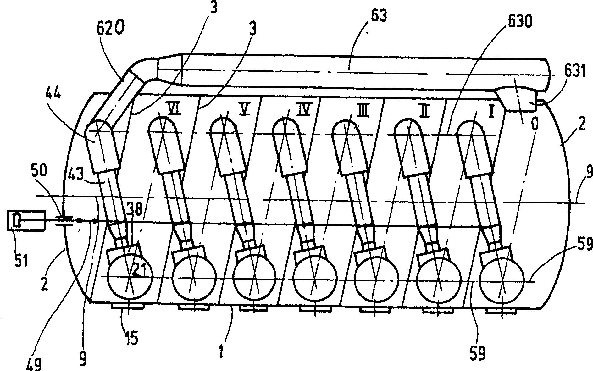
[0074] exist Figure 9 The high temperature piece dyeing machine shown with nine J-boxes is in principle the same as Figure 8The high temperature piece dyeing machine shown corresponds accordingly. Identical parts therefore bear the same reference numerals and will not be described again. as a pair Figure 8 The addition of the piece dyeing machine is that, according to Figure 9 The piece dyeing machine also has a mechanism for supplying superheated steam from the steam source 90 to the processing container 1 and for extracting air-steam mixture from the processing container 1. The back of the steam source 90 is connected to a steam superheater 93 through a steam trap 91 and a pressure reducing valve 92, and a 2-way fitting 95 is connected to the top through a regulating valve 94, and the fitting is selectively supplied to the inner space of the processing vessel and passed through a 96 shown The duct distributor supplies superheated steam to the delivery nozzle 38 of ea...
Embodiment 3
[0083] use Figure 9 The high-temperature piece dyeing machine can also carry out a subsequent drying step after the reactive dyeing has been carried out, for example on cotton knitted fabrics according to the washing-rinsing process in the circulatory system.
[0084] For this reason, the following processing steps are carried out on the piece dyeing machine:
[0085] 1. Heating of textile and loaded dye liquor, including treatment vessel 1 and components arranged inside.
[0086] After switching on the blower unit 21 and the drives of the deflection guide rollers 52 involved in the circulation of the rope-like fabric, the pivotably arranged guide roller 57 is pressed against the rope-like fabric by means of a pneumatic cylinder 58 ( FIG. 6 ). By the pneumatic cylinder 51 ( figure 2 ) The reciprocating motion of the feeding elbow 44 produced ensures the orderly stacking of rope-like fabrics in the J-shaped box I-IX for circulation.
[0087] The fabric is rapidly heated to...
PUM
 Abstract
Description
Claims
Application Information
 - R&D
- Intellectual Property
- Life Sciences
- Materials
- Tech Scout
- Unparalleled Data Quality
- Higher Quality Content
- 60% Fewer Hallucinations
Browse by: Latest US Patents, China's latest patents, Technical Efficacy Thesaurus, Application Domain, Technology Topic, Popular Technical Reports.
© 2025 PatSnap. All rights reserved.Legal|Privacy policy|Modern Slavery Act Transparency Statement|Sitemap|About US| Contact US: help@patsnap.com