
Quartz reflecting polarization beam splitting grating with 1550 nanometer wavelength

A reflective polarization, beam splitting grating technology, applied in the direction of diffraction grating

Inactive Publication Date: 2006-07-12
SHANGHAI INST OF OPTICS & FINE MECHANICS CHINESE ACAD OF SCI
View PDF0 Cites 13 Cited by
  • Summary
  • Abstract
  • Description
  • Claims
  • Application Information

AI Technical Summary

Problems solved by technology

But as far as we know, no one has given the design parameters of the immersed high-density quartz reflective polarization beam-splitting grating for the 1.55 micron band of optical fiber communication

Method used


Image

  • Quartz reflecting polarization beam splitting grating with 1550 nanometer wavelength
  • Quartz reflecting polarization beam splitting grating with 1550 nanometer wavelength
  • Quartz reflecting polarization beam splitting grating with 1550 nanometer wavelength

Examples


Embodiment Construction

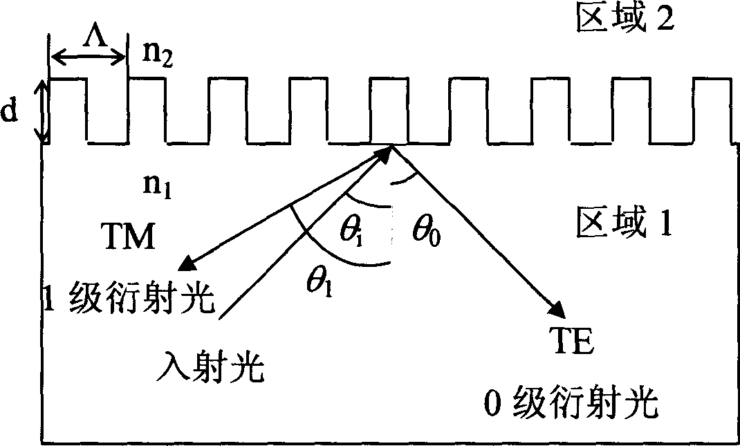
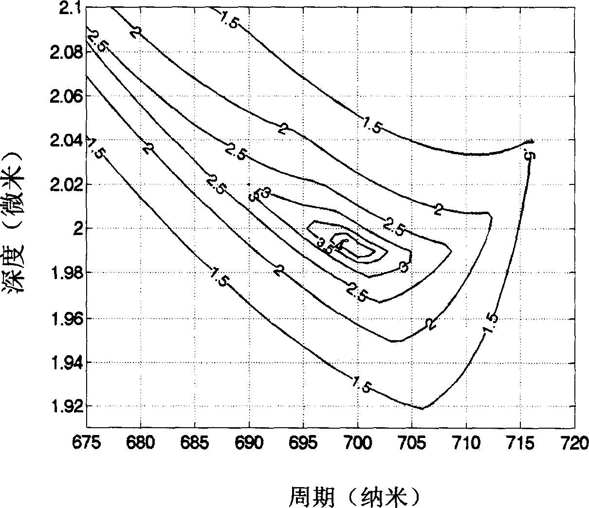
[0021] Using micro-optical technology to manufacture high-density rectangular polarization beam-splitting gratings, first deposit a layer of metal chromium film on a dry and clean fused silica substrate, and evenly coat a layer of positive photoresist on the chromium film (Shipley, S1818, USA ). The grating is then recorded holographically (see Figure 6), the He-Cd laser emits two beams of plane waves with a wavelength of 0.441 μm to form an interference field on the substrate at an angle of 2θ. The spatial period of the grating, that is, the distance between adjacent stripes, can be expressed as Λ=λ / (2*sinθ), where λ is the wavelength of the recording light. The larger the recording angle θ, the smaller Λ, so by changing the size of θ, the period of the grating can be controlled (the period value can be designed by the above extinction ratio and efficiency diagram), and high-density grating can be recorded. Next, after development, the photoresist pattern is transferred fr...


PUM

PropertyMeasurementUnit
Etching depthaaaaaaaaaa
Cycleaaaaaaaaaa
Etching depthaaaaaaaaaa

Abstract

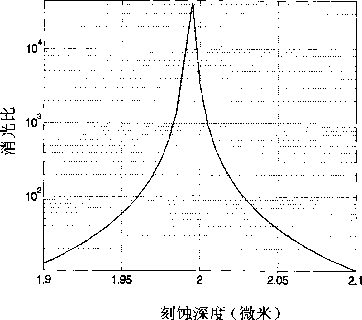
The quartz reflection-polarization beam-splitting grating of 1550 nano wavelength for optical fiber communication is characterized in: 692-710 nanometer period, 1.985-2.005micron etching depth, and 1 / 2 duty ratio. It can split the light with vertical TE and TM polarization modes into different direction to achieve that the extinction ratio for 0-level and 1-level all more than 100, and the 0 / 1-level diffraction efficiency of TE / Tm polarized light more than 99.02% / 99.27%. This invention can cut the cost greatly for large-scale production.

Description

technical field [0001] The invention relates to a polarization beam-splitting grating device in the optical fiber communication band, in particular to a back-incidence (or immersion) high-density deep-etched quartz reflection polarization beam-splitting grating with a wavelength of 1550 nanometers. Background technique [0002] Information Age With the rapid development of science and technology, human society is evolving into an information society. The amount of information transmission is expanding at an accelerated rate, which requires the transmission network to become larger and larger. The existing network built on the physical layer with electricity as the basic transmission medium has reached its limit, lacking bandwidth, slow speed, and poor flexibility. With the transformation from the "Era of Electronic Communication" to the "Era of Information Communication", people demand that a large amount of information can be obtained at any place, any time and in any way ...

Claims


Application Information

Patent Timeline
IPC IPC(8): G02B5/18
Inventor 周常河王博
Owner SHANGHAI INST OF OPTICS & FINE MECHANICS CHINESE ACAD OF SCI
Learn More