Electro-optic device

An electro-optical device, voltage technology, applied in static indicators, instruments, etc., can solve the problem of display unit and drive circuit becoming larger, and achieve the effect of preventing increase, reducing flicker and unevenness

Inactive Publication Date: 2006-07-19
INT BUSINESS MASCH CORP
View PDF1 Cites 9 Cited by
  • Summary
  • Abstract
  • Description
  • Claims
  • Application Information

AI Technical Summary

Problems solved by technology

This is likely to result in larger display units and drive circuits

Method used


Image

  • Electro-optic device
  • Electro-optic device
  • Electro-optic device

Examples


Embodiment Construction

[0021] An electro-optical device including a driving circuit is described according to an embodiment of the present invention, an example of a liquid crystal display device is given, and drawings are referred to.

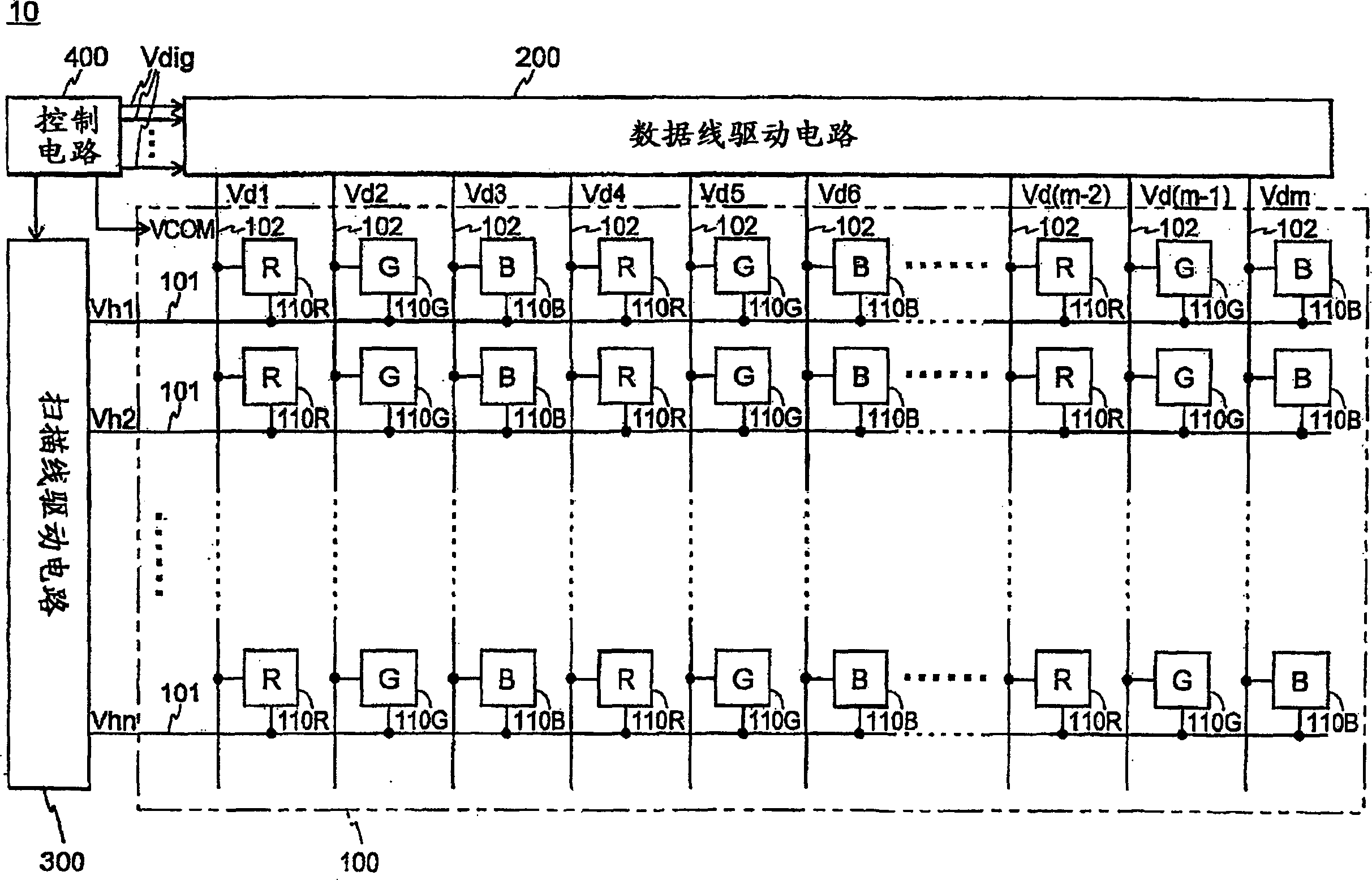
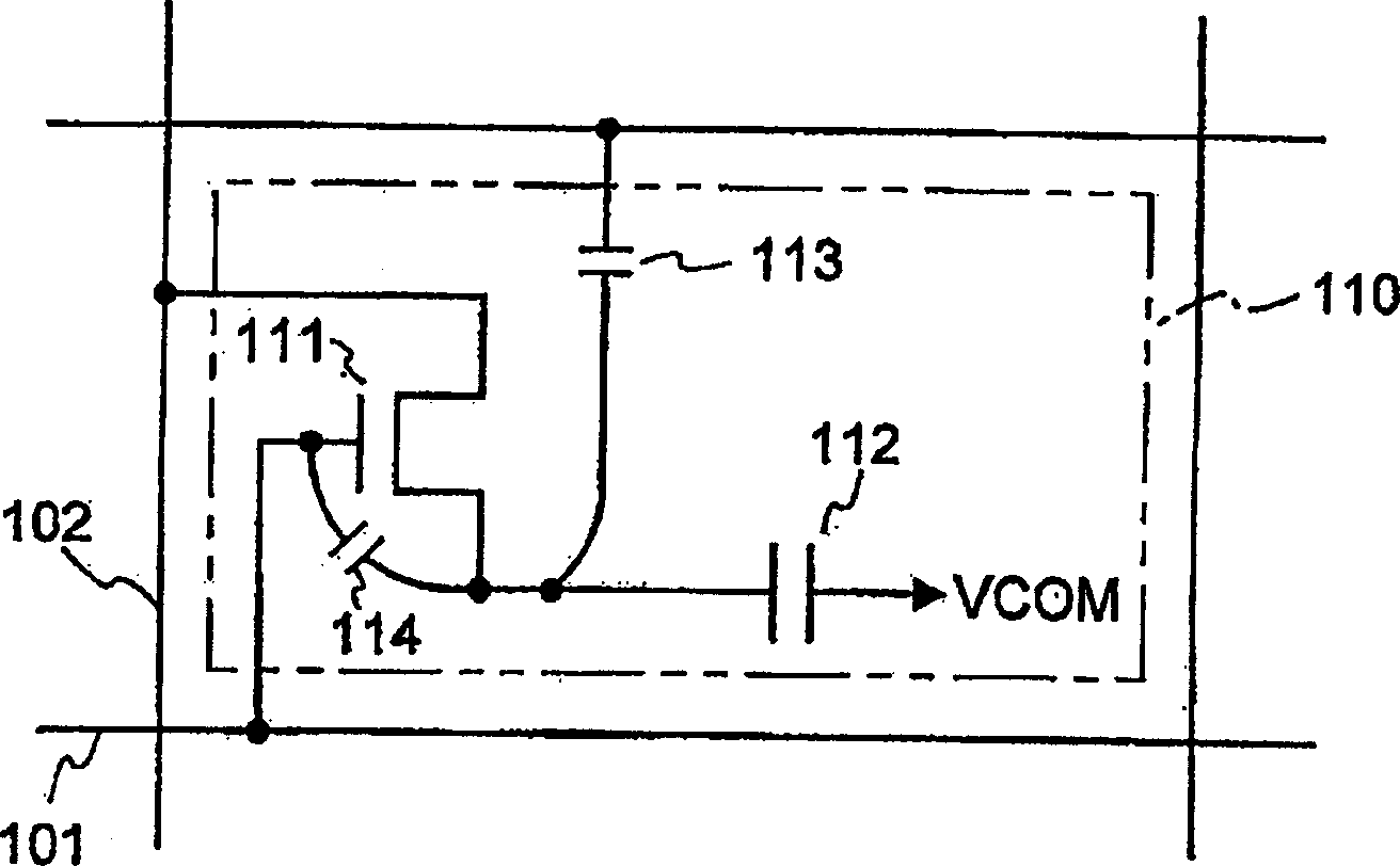
[0022] figure 1 Shown is a configuration diagram of the overall configuration of the liquid crystal display device 10 . This liquid crystal display device includes a liquid crystal panel 100 , a data line driving circuit 200 as a driving circuit, a scanning line driving circuit 300 , and a control circuit 400 . The liquid crystal panel 100 has a plurality of scan lines 101 and a plurality of data lines 102 . A plurality of pixel circuits 110 ( 110R, 110G, and 110B) are arranged in a matrix of n rows×m columns, respectively corresponding to intersections of the scan lines 101 and the data lines 102 . The number of pixel circuits 110 is, for example, 768 rows×3,072 columns.

[0023] Each pixel circuit 110 is a sub-pixel corresponding to any R color, G color, or B c...


PUM


Abstract

Disclosed is a drive circuit for an electro-optic device which includes a plurality of scan lines, a plurality of data lines, and a plurality of pixel circuits arranged corresponding to intersections between each of the scan lines and each of the data lines. The drive circuit includes a compensation voltage outputting circuit which, corresponding to a plurality of representative data lines selected out of the plurality of data lines, outputs compensation voltages which are obtained by compensating for differences in voltage characteristics among pixel circuits corresponding to the representative data lines; a reference voltage distributing circuit for outputting a plurality of reference voltages on the basis of at least two of the compensation voltages; and a data voltage outputting circuit for outputting data voltages based on the reference voltages respectively to the data lines.

Description

technical field [0001] The present invention relates to a drive circuit for an electro-optical device, the electro-optic device, an electronic device and a driving method for the electro-optic device. Background technique [0002] Heretofore, liquid crystal display devices have been known as examples of electro-optical devices. The liquid crystal display device includes a display unit, a drive circuit and an adjustment circuit. The display units are arranged at intersections between each of the plurality of scan lines and each of the plurality of data lines, so the display units are arranged in a matrix. Each display unit includes pixel circuits such as thin film transistors (hereinafter referred to as "TFTs") and display electrodes. The drive circuit supplies voltage to the TFT. An adjustment circuit is provided to each drive circuit, and adjusts the reference voltage according to the influence of the TFT and display electrode parasitic capacitance on the electrode volta...

Claims


Application Information

Patent Timeline
Patent Type & Authority Applications(China)
IPC IPC(8): G09G3/36G09G3/20G02F1/133
CPCG09G2320/0233G09G3/3688G09G2320/0223
Inventor 土桥森行
Owner INT BUSINESS MASCH CORP
Why Eureka
Try Eureka