Transverse fabric clamping and tensioning device

A tensioning device and fabric technology, applied in the field of stretching device and fabric horizontal clamping, to achieve the effect of ensuring processing quality and reasonable structure

Inactive Publication Date: 2006-07-26
JIANGSU DADAO MACHINE GROUP
View PDF0 Cites 14 Cited by
  • Summary
  • Abstract
  • Description
  • Claims
  • Application Information

AI Technical Summary

Problems solved by technology

[0003] The purpose of the present invention is to provide a horizontal fabric clamping and tensioning device with a reasonable structure, which can effective

Method used


Image

  • Transverse fabric clamping and tensioning device
  • Transverse fabric clamping and tensioning device
  • Transverse fabric clamping and tensioning device

Examples


Example Embodiment

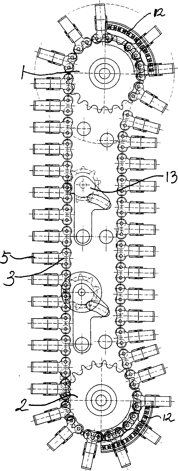
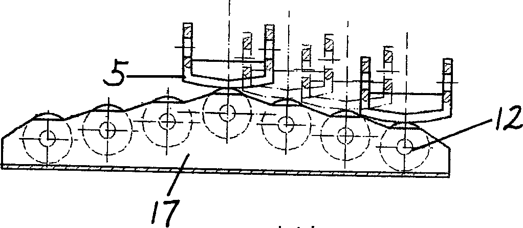
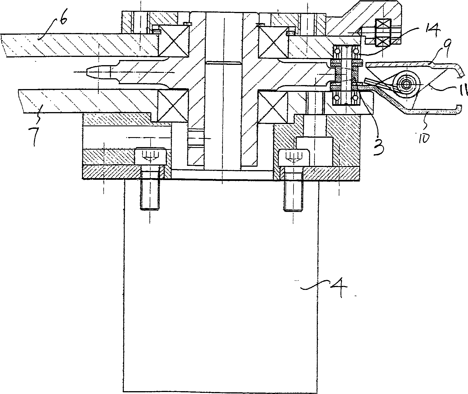
[0014] A horizontal fabric clamping and tensioning device, a chain 3 driven by sprocket wheels 1 and 2, the sprocket is driven by a stepping motor 4, each link of the chain 3 is equipped with a fabric controlled by a switch mechanism to open and clamp Clamp 5, upper and lower cover plates 6, 7 are installed on both sides of the chain, and chain track grooves 8 are provided on the upper and lower cover plates to limit the chain movement track. The chain track groove 8 is recessed inward toward the side of the fabric, so that the fabric clip 5 can further tighten the fabric 15. The fabric clip 5 is an elastic clip, which is composed of upper and lower clips 9, 10 and a buckle spring 11. The fabric clip switch mechanism is a top-opening switch device arranged on the upper cover plate 6. The top-opening switch device has a plurality of bearings 12 installed on the upper cover plate 6 outside the sprockets at both ends and arranged along the chain movement direction. The multiple beari...


PUM


Abstract

This invention discloses a chain with chain wheel driving, its traversing lining is gripped, and it has the strain equipment. The chain link has a switch device which controls the open and grip of the lining nip, the two sides of the chain are covered with cover boards, the cover boards are arranged the chain orbit grooves that limit the running contrail of the chain. In this invention, the quilter, the embroider machine, the dye machine, the printing machine and others can avoid the lining from contracting horizontally by drawing or ripping effect of the lining during their working course, so that protect the processing quality.

Description

Technical field: [0001] The invention relates to a device for laterally clamping and pulling fabrics such as quilting machines, quilting embroidery machines, cloth dyeing machines and printing machines. Background technique: [0002] Existing machines (such as quilting machines, quilting embroidery machines, cloth dyeing machines, printing machines, etc.) for quilting, quilting embroidery, dyeing, printing, etc. of fabrics generally have nip rollers for the longitudinal direction of the fabric (Y However, since there is no clamping and tensioning device in the horizontal direction during processing, it is easy to produce lateral (ie X-direction) shrinkage during work, which affects the processing effect. Invention content: [0003] The object of the present invention is to provide a horizontal fabric clamping and tensioning device with a reasonable structure, which can effectively solve the problem of lateral fabric shrinkage during the working process of quilting, quiltin...

Claims


Application Information

Patent Timeline
IPC IPC(8): D06C3/02D06B23/04
Inventor 施林龙
Owner JIANGSU DADAO MACHINE GROUP
Why Eureka
Try Eureka