Multi-connected air conditioning unit with liquid pump to supply refrigerant

A multi-connected air conditioner and liquid pump technology, which is applied in the direction of air-conditioning systems, refrigerators, heating methods, etc., can solve the problems of poor system regulation and controllability, limited range of multi-connected systems, and poor oil return performance of the system. , to achieve the effect of improving regulation performance and controllability, facilitating flushing and carrying, and improving oil return performance

Inactive Publication Date: 2006-07-26
TSINGHUA UNIV
View PDF1 Cites 13 Cited by
  • Summary
  • Abstract
  • Description
  • Claims
  • Application Information

AI Technical Summary

Problems solved by technology

[0003] Aiming at the deficiencies and defects of the prior art, the present invention provides a liquid pump liquid supply multi-connected air conditioner unit to solve the problem of limited range of multi-connected systems, poor system

Method used


Image

  • Multi-connected air conditioning unit with liquid pump to supply refrigerant
  • Multi-connected air conditioning unit with liquid pump to supply refrigerant
  • Multi-connected air conditioning unit with liquid pump to supply refrigerant

Examples


Embodiment 1

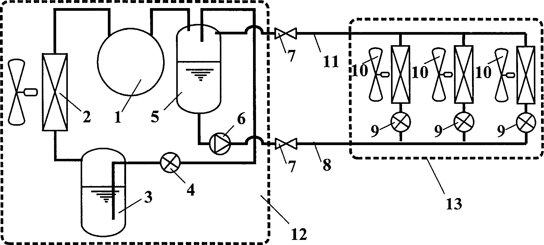
[0017] figure 2 The structural principle diagram of the liquid pump liquid supply multi-connected air conditioner unit provided by the present invention, according to figure 2 Connect the exhaust port of the compressor 1 to the inlet of the air-cooled outdoor heat exchanger 2 through the refrigerant pipeline, connect the high-pressure accumulator 3 to the outlet of the outdoor heat exchanger 2, and use the refrigerant pipeline to connect the Outdoor unit throttling device - one end of the float valve 4 is connected to the bottom outlet of the high-pressure liquid reservoir 3, and the other end is connected to the inlet of the low-pressure liquid storage circulator 5, and the upper outlet of the low-pressure liquid storage circulator 5 is connected to the compressor 1 to form the refrigeration cycle of the outdoor unit 12. In the outdoor unit 12, the suction port of the liquid pump 6 is connected to the bottom outlet of the low-pressure liquid storage circulator 5, and the o...

Embodiment 2

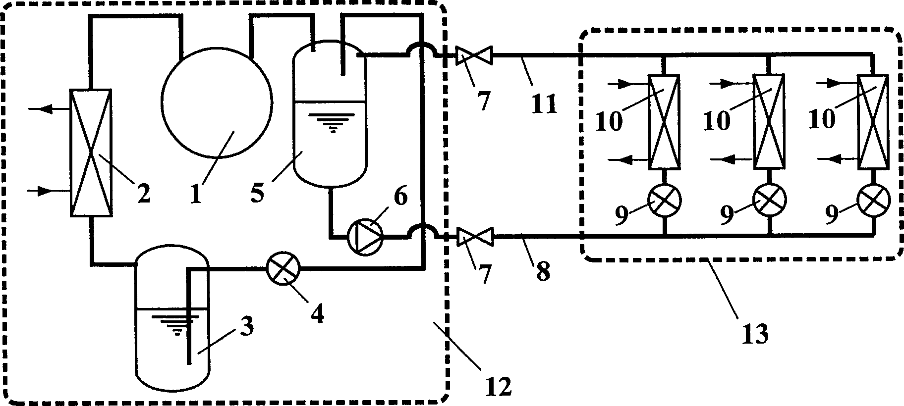
[0019] image 3 Structural schematic diagram of multi-connected air conditioner unit with liquid pump for liquid supply using water-cooled heat exchanger for indoor unit. according to image 3 Connect the exhaust port of the compressor 1 to the inlet of the water-cooled outdoor heat exchanger 2 through the refrigerant pipeline, connect the high-pressure accumulator 3 to the outlet of the outdoor heat exchanger 2, and use the refrigerant pipeline to connect the outdoor Machine throttling device - one end of the electronic expansion valve 4 is connected to the bottom outlet of the high-pressure liquid accumulator 3 and the other end is connected to the inlet of the low-pressure liquid storage circulator 5, and the upper outlet of the low-pressure liquid storage circulator 5 is connected to the compressor 1 The suction port forms the refrigeration cycle of the outdoor unit. In the outdoor unit 12, the suction port of the liquid pump 6 is connected to the bottom outlet of the lo...


PUM


Abstract

The invention relates to a liquid pump liquid supply multiple air-conditioning unit, which uses the liquid pump liquid supply to process the cold supply of multiple rooms. The invention comprises the indoor machine and the outdoor machine. It is characterized in that: the outdoor machine comprises a low pressure cycle liquid storage, a liquid pump, and a outdoor machine throttle device, while it uses the liquid pump to pressurize the low pressure liquid coolant generated by the outdoor machine to be fed into indoor heat exchangers of indoor machine via the pipeline to supply cold and form the liquid pump liquid supply multiple refrigeration cycle. Compared to present technique, the invention increases the pressure of the coolant at the inlet of electric expansion valve besides the indoor machine heat exchanger and the pressure difference uniformity between two ends of each expansion valve, improve the safety and regulation property of indoor expansion valve and the reflux property of system, and effectively enlarge the application of multiple system.

Description

technical field [0001] The invention relates to a liquid pump liquid supply multi-connected air conditioner unit, which belongs to the technical field of refrigeration and air conditioning. It is especially suitable for the occasions where multiple units are used for air conditioning and cooling in multiple rooms and within a large cooling radius. Background technique [0002] With the development of air-conditioning technology, multi-connected air-conditioning (that is, multi-connected) systems have shown increasing advantages in energy consumption and performance, and because of their energy-saving design, control, easy operation and high reliability, In recent years, it has been widely used in small office buildings, shopping malls, restaurants and residences, and has developed rapidly. The multi-connected system has the following advantages: ①. There are various types of indoor units, and each unit can be independently controlled, started and stopped freely, and the ope...

Claims


Application Information

Patent Timeline
IPC IPC(8): F24F1/00F25B41/04
Inventor 石文星余延顺李先庭王宝龙
Owner TSINGHUA UNIV
Why Eureka
Try Eureka